Tools for Designers:
Power Distribution Network Analyzer
Sierra Circuits' Power Distribution Network Analyzer lets you quickly calculate your power network's target impedance, fastest rise time (tr), and maximum frequency (fm).
Try This New ToolSierra Circuits’ Power Distribution Network Analyzer determines the target impedance (Zt) for a PDN based on the power rail voltage, maximum power rail current, acceptable voltage ripple, and switching current.
The power network in your circuit board layout should ensure stable power delivery. Sometimes, high switching speeds can lead to voltage fluctuations, crosstalk, and EMI in your power system. This can hinder the performance and reliability of your PCB.
You can overcome these challenges by maintaining the power supply’s AC impedance below the designated target impedance.
Our PDN analysis tool allows you to quickly calculate your power network’s target impedance (Zt), fastest rise time (tr), and maximum frequency (fm).
Features of the PDN Analyzer
- Supports multiple power rails: You can add multiple power rails per your design requirements and the data can be viewed in tabular format.
- Allows you to download the data: Export the entire table with inputs and calculated results to an Excel spreadsheet.
- Facilitates calculation in multiple units: You can switch between various units for voltage, current, impedance, rise time, and frequency to match your project requirements.
- Provides information on input and output parameters: To read the definitions of any input and output parameters, simply click the help (?) button.
How to use the Power Distribution Network Analyzer
To calculate the target impedance, you need to enter the following parameters:
- Power rail voltage: The voltage supplied by the rail.
- Acceptable voltage ripple %: The allowed fluctuation in voltage.
- Maximum power rail current: The maximum expected current draw on the rail.
- Switching current % (of maximum power rail current): The percentage of current attributed to high-frequency switching.
To calculate the fastest rise time, you have to enter the maximum frequency. Similarly, to compute the max. frequency (fm)you need to input the fastest rise time (tr).
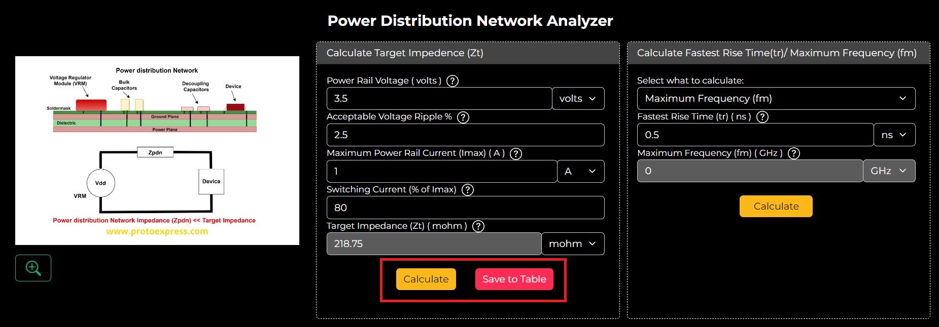
Step 1: Enter the Power Rail Voltage, Acceptable Voltage Ripple %, Maximum Power Rail Current (Imax), and Switching Current (% of Imax), and click Calculate to view the results.
If you want to calculate Zt for a different power rail, click Save to Table and repeat step 1. The initial results will be saved as shown below.
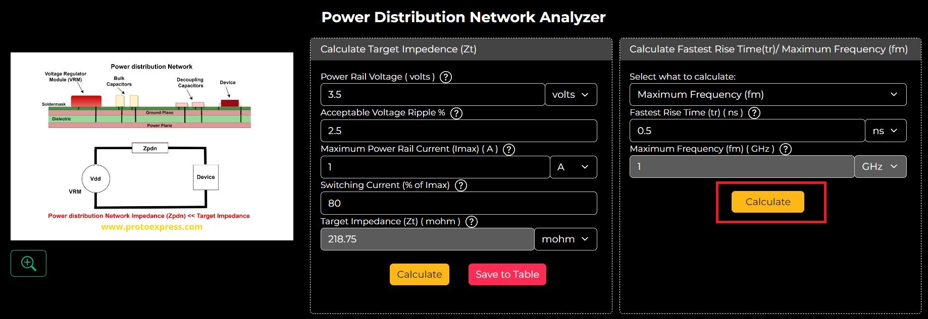
Step 2: Enter the Fastest Rise Time and hit calculate to compute the Maximum Frequency. The default value for the Fastest Rise Time is 0.5 ns. However, you can change its value according to your requirements.
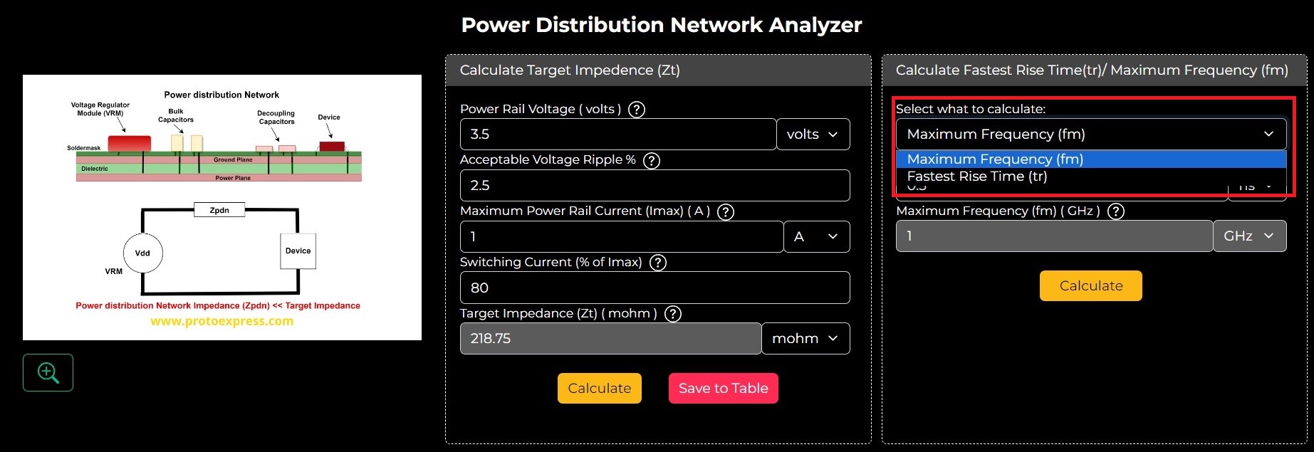
Step 3: To determine tr you need to select the option Fastest Rise Time from the drop-down.
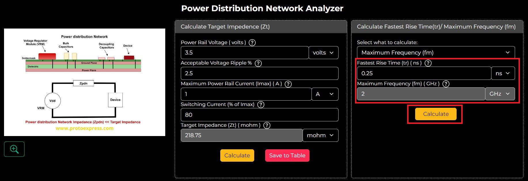
Next, enter the value of Maximum Frequency and hit Calculate.
Step 4: If you want to download the results in Excel format, hit Export to Excel.
The Power Distribution Network Analyzer offers a comprehensive solution to optimize power delivery in your PCB layout.
This advanced circuit board design tool empowers you to overcome challenges associated with voltage fluctuations, crosstalk, and EMI by accurately determining the target impedance. Visit our designer’s tools page to explore all our advanced PCB design tools.
Explore the tool now.
Sierra Circuits has developed easy-to-use tools for PCB designers and electrical engineers at every stage of circuit board development.
Fabrication, Procurement, & Assembly. PCBs fully assembled in as fast as 5 days.
- Bundled together in an entirely-online process
- Reviewed and tested by Engineers
- DFA & DFM Checks on every order
- Shipped from Silicon Valley in as fast as 5 days
Fabrication. Procurement & Assembly optional. Flexible and transparent for advanced creators.
- Rigid PCBs, built to IPC-6012 Class 2 Specs
- 2 mil (0.002″) trace / space
- DFM Checks on every order
- 24-hour turn-times available
Complex technology, with a dedicated CAM Engineer. Stack-up assistance included.
- Complex PCB requirements
- Mil-Spec & Class 3 with HDI Features
- Blind & Buried Vias
- Flex & Rigid-Flex boards


