Contents

On-demand webinar
How Good is My Shield? An Introduction to Transfer Impedance and Shielding Effectiveness
by Karen Burnham
Power electronics PCBs are designed to handle elevated currents and voltages in applications like electric vehicles (EVs) and renewable energy systems. Selecting the right materials and components for these boards is crucial for a successful prototype.
In this blog, you will learn how to choose the right parts and materials for your power electronic PCB projects.
This is a must-read article for power electronics engineers looking to optimize their designs.
Highlights:
When picking materials and components for your power electronics boards:
- Opt for materials with high thermal conductivity, like Rogers RT laminate (1.44 W/m/K), to handle high power.
- Utilize buck, boost, or buck-boost converters in portable devices for efficient voltage regulation.
- Choose low ESR capacitors and low DCR inductors to minimize power losses.
- Adopt SiC for high-voltage applications like EVs and industrial equipment.
7 tips for choosing materials for power electronics PCBs
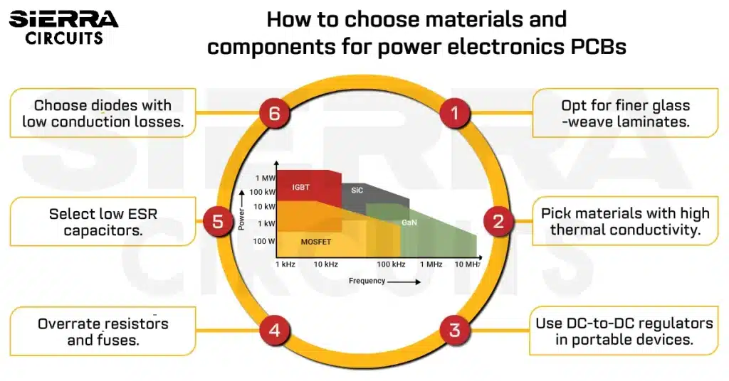
In high-power electronics, materials with higher thermal conductivity are necessary to efficiently dissipate heat, minimize temperature rise, and protect components. Traditional PCB materials like FR4 are inadequate for these applications.
- Opt for materials with a finer glass weave and higher resin content for high-voltage designs. Finer glass weave provides better electrical insulation, while the resin ensures the required mechanical strength and dielectric properties.
- Prefer higher resin content to mitigate the risks of voiding (gaps or air pockets) between layers and improve material integrity in multilayer PCBs. Voids can lead to increased susceptibility to conductive anodic filamentation (CAF) as moisture and contaminants can accumulate in these voids.
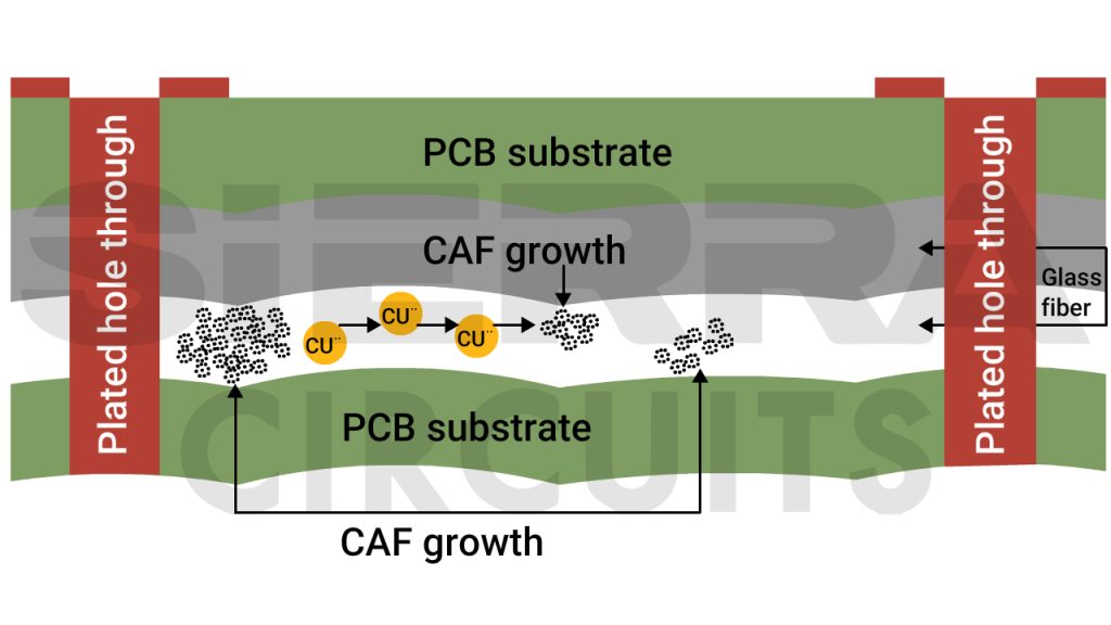
Voids can lead to increased susceptibility to CAF. High-density PCBs are prone to CAF failure, leading to reduced PCB line spacing. See the importance of PCB line spacing, creepage, and clearance to learn more.
- Prefer higher resin content to mitigate the risks of voiding (gaps or air pockets) between layers and improve material integrity in multilayer PCBs. Voids can lead to increased susceptibility to conductive anodic filamentation (CAF) as moisture and contaminants can accumulate in these voids.
-
- Avoid low resin content, which can also increase the risk of electromigration due to the poor electrical insulation properties of air or void-filled spaces.
- Use finer glass weaves like 1080, 2113, or 2116 for better resin penetration, which aids in preventing void formation.
- Select materials with phenolic curing agents rather than DICY (dicyandiamide). Phenolic agents offer better CAF inhibition at high voltages. DICY-based materials, despite having higher glass transition temperatures (Tg), are more prone to failure under high voltage gradients.
- For designs operating at a higher current, prioritize materials with higher thermal conductivity and Tg to manage DC losses and ensure efficient thermal performance and long-term reliability.
- Choose Rogers RT laminate that offers a high thermal conductivity of up to 1.44 W/m/K. It offers better heat management and reduced temperature rise, ideal for high-power applications. See Rogers PCBs to learn more.

High thermal conductivity PCB materials offer a greater heat dissipation rate in power electronics.
- Choose Rogers RT laminate that offers a high thermal conductivity of up to 1.44 W/m/K. It offers better heat management and reduced temperature rise, ideal for high-power applications. See Rogers PCBs to learn more.
- Pick materials with similar CTEs to minimize mechanical stress during fabrication. This also ensures that materials expand and contract at the same rate during high power or temperature fluctuations.
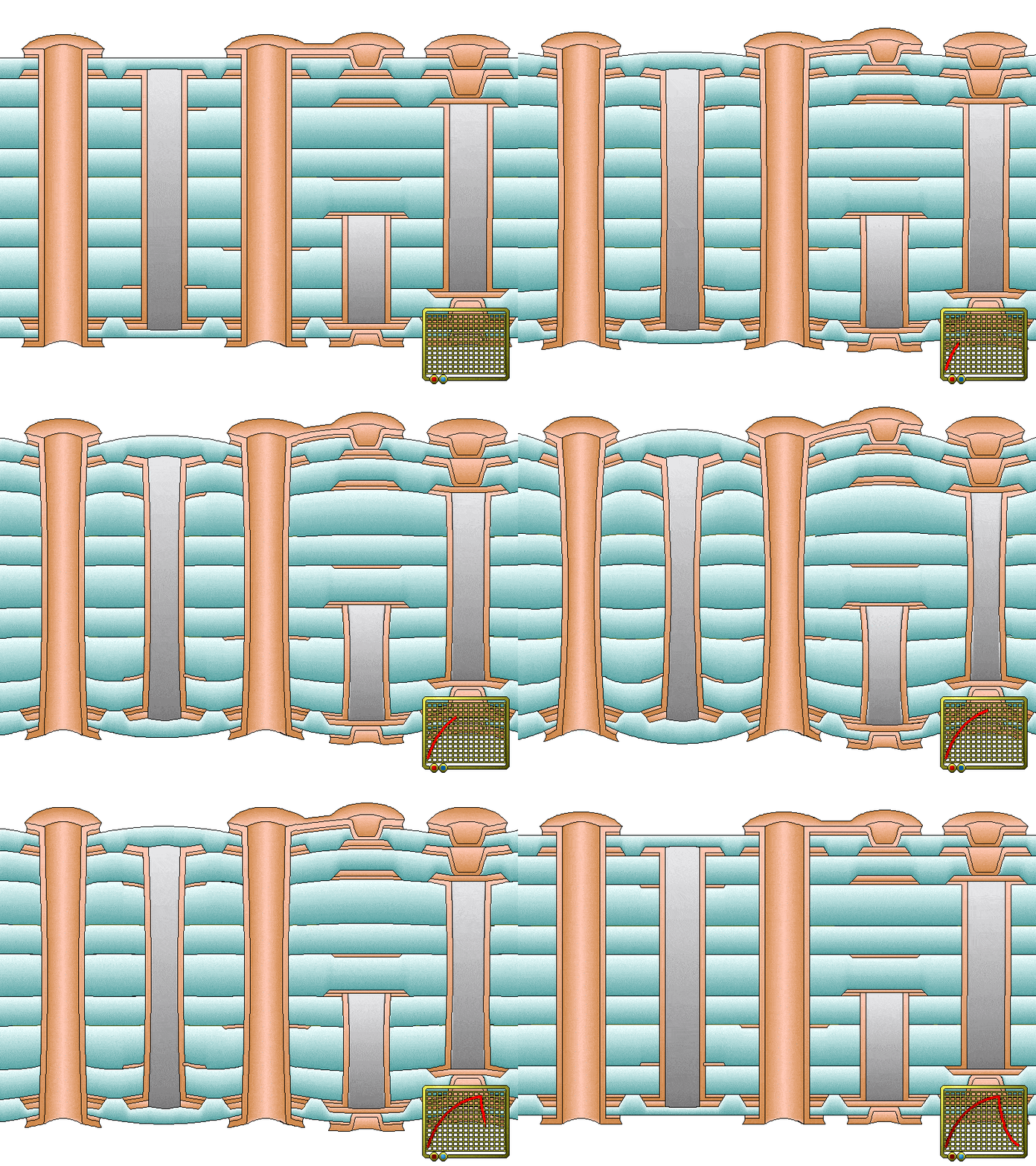
Illustration of how a PCB expands and contracts during temperature variations. - Evaluate copper weight and material thermal conductivity to manage heat effectively and assess board equilibrium temperature under steady-state conditions. Refer to IPC-2152 for general thermal design guidance, followed by full evaluation tests to ensure material recommendations are optimized for your design.
- Carefully specify material requirements to manufacturers and verify datasheets for compatibility with your power electronics design needs.
- Refer to standards like IEC-60950-1, IPC-2221, and standard test methods, including IEC 60112, UL 746A, and ASTM D3638, to choose materials based on their comparative tracking index (CTI) for high voltage designs.
CTI helps evaluate material performance by measuring its resistance to electrical tracking. CTI values are further categorized into performance level categories (PLC) based on their degradation voltage.
| Performance level categories | Voltage (V DC) |
|---|---|
| 0 | >600 |
| 1 | 400-599 |
| 2 | 250-399 |
| 3 | 175-249 |
| 4 | 100-174 |
| 5 | <100 |
The PLC provides a clear understanding of material suitability for different operating conditions.
Download our design guide to learn how to select the right materials for your PCBs.
PCB Material Design Guide
9 Chapters - 30 Pages - 40 Minute ReadWhat's Inside:
- Basic properties of the dielectric material to be considered
- Signal loss in PCB substrates
- Copper foil selection
- Key considerations for choosing PCB materials
Download Now
10 best component selection practices for power electronics
Choosing PCB components for power electronics is essential to achieve optimal performance in prototypes.
1. Verify the lifecycle status of the components
When picking components for a power electronics board, consider their lifecycle status. If a component reaches the end of its lifecycle before production begins, it causes disruption, leading to delays and the need for re-engineering.
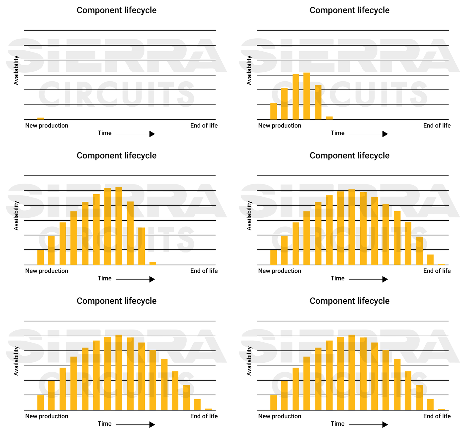
Check for component availability before sending the design files to the fabrication house. This is critical as some parts might be out of stock at the time of ordering them.
For tips on cutting your PCBA expense, see how to reduce your PCB assembly costs.
How to check the lifecycle status
Leading distributors like Mouser and DigiKey label component lifecycles (active, NRND, EOL/obsolete) to help engineers avoid delays and redesigns.
Manufacturers update part statuses based on technology and market changes, notifying distributors with part change notifications (PCNs).
To eliminate potential supply chain disruptions, Sierra Circuits offers a PCB component sourcing and stocking facility. By choosing this service, you eliminate the risk of counterfeit and low-quality parts, enabling you to concentrate on optimizing your PCB design.
2. Implement a linear power supply for noise-sensitive applications
Linear AC to DC power converters produce minimal electrical noise compared to switched-mode power supplies (SMPS). Their simplicity and minimal component requirements make them suitable for simple and low-power applications.
However, they are not recommended for high-power applications due to low efficiency and significant heat generation, which can pose thermal management challenges in your PCBs.
4 guidelines to incorporate linear regulators in your PCB layout
- Choose regulators with low thermal resistance to prevent overheating and ensure stable operation within their optimal temperature range.
- For multi-regulator systems, use LDO (low dropout) regulators downstream of switching regulators to further step down the voltage.
- Use an input filter capacitor to suppress noise from the power source. This ensures a stable input voltage for the LDO, as it relies on a clean input to deliver a low-noise output.
- Implement effective heat dissipation strategies, such as heatsinks, thermal vias, or heat-spreading planes. Ensure adequate board area for these features. This is especially crucial in sealed enclosures with limited airflow to prevent overheating. Make a note that this makes the board bulky.
- Place temperature-sensitive components away from linear supplies.
3. Integrate switched-mode power supply (SMPS) in heat-sensitive environments
Switched-mode power supplies convert AC power to DC by rapidly switching components on and off. They reduce energy losses, making them an ideal choice for high-power applications.
Their superior efficiency compared to linear power supplies reduces the need for extensive thermal management.
4 SMPS design tips for power electronics engineers
- Include a solid, continuous ground plane and effective shielding in your layout to minimize EM noise generated by SMPS.
- Strategically place ground vias to minimize ground bounce, which can result from rapid switching in SMPS circuits. Ground bounce creates temporary potential differences across the ground plane, potentially affecting distant components and causing instability.
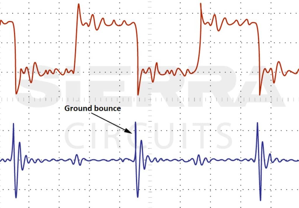
Rapid switching in SMPS can cause ground bounce in PCBs - Implement effective filtering techniques to reduce ripple voltage and EMI. Proper filtering minimizes capacitive and inductive coupling between tracks, preventing unwanted noise.
- Incorporate filtering and shielding strategies to prevent SMPS noise from propagating back into the power line. If unmanaged, this noise can be conducted through the main supply, potentially affecting other devices connected to the same circuit.
Despite their more complex design, SMPS ensure efficiency levels that surpass even the best linear power supplies. However, their high-frequency switching generates EMI, which can interfere with electrical signals, damage electronic components, and cause signal integrity issues.
As a result, linear technology is often preferred in electromedical and laboratory equipment.
4. Prioritize the use of DC-to-DC power converters in portable devices
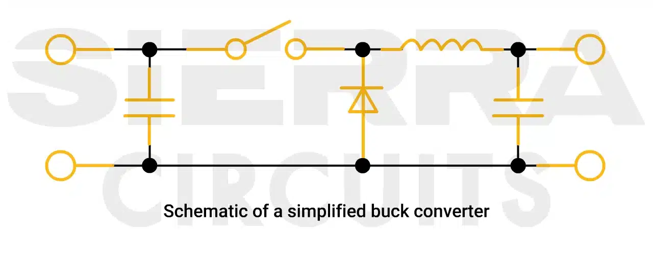
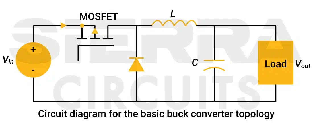
DC-to-DC converters are commonly used to adjust voltage levels, either stepping them up or down as needed. These regulators are suitable for portable devices and automotive applications where efficient voltage regulation is critical.
Buck converters are ideal for stepping down voltage, while boost converters are used to step up voltage. Buck-boost converters offer flexibility, allowing for either voltage increase or decrease depending on the control circuit.
5. Implement an isolated switching converter for high current boards
The power topology of individual regulator circuits and the overall power distribution system is determined by the input and output power requirements. Each regulator circuit in the power tree serves a different purpose, depending on the voltage range and current demands.
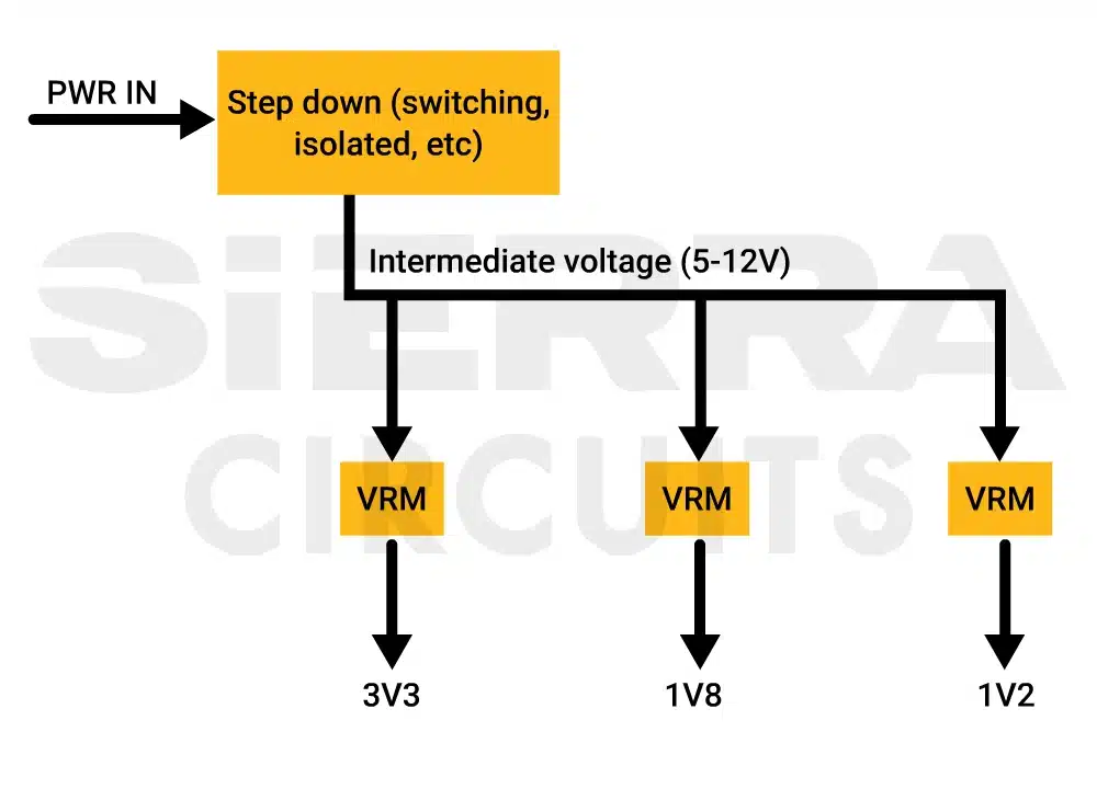
Use a switching regulator for large voltage step-up or step-down, as it stores and releases power using reactive elements instead of dissipating power through resistive elements that convert it into heat.
4 best topology choices for a power electronics circuit
- Implement an LDO for small voltage step-downs, even with moderate currents, to achieve simpler and more cost-effective designs.
- Use a non-isolated buck or boost converter for large voltage step-ups or step-downs with moderate current. It provides efficient power conversion without the need for isolation.
- Choose an isolated switching converter (such as LLC resonant, flyback, or bridge) with a high-power transformer for high current at standard voltages, ensuring balanced efficiency, safety, and noise reduction.
- Select a multiphase converter for a broad power range and low ripple current, ideal for applications requiring stable power output.
6. Choose switches and diodes with low conduction losses
The primary components dictating the topology and functionality of power electronics circuits are switches and diodes. Switches and diodes play a critical role in component selection for power electronics, as they directly impact efficiency and heat management.
| Components | Types | Examples |
|---|---|---|
| Switches | Uncontrolled | Thyristors |
| Controlled | MOSFETs, IGBTs, and GaN devices | |
| Diodes | Conventional | Silicon diodes |
| Reverse-blocking | Schottky diodes and SiC diodes |
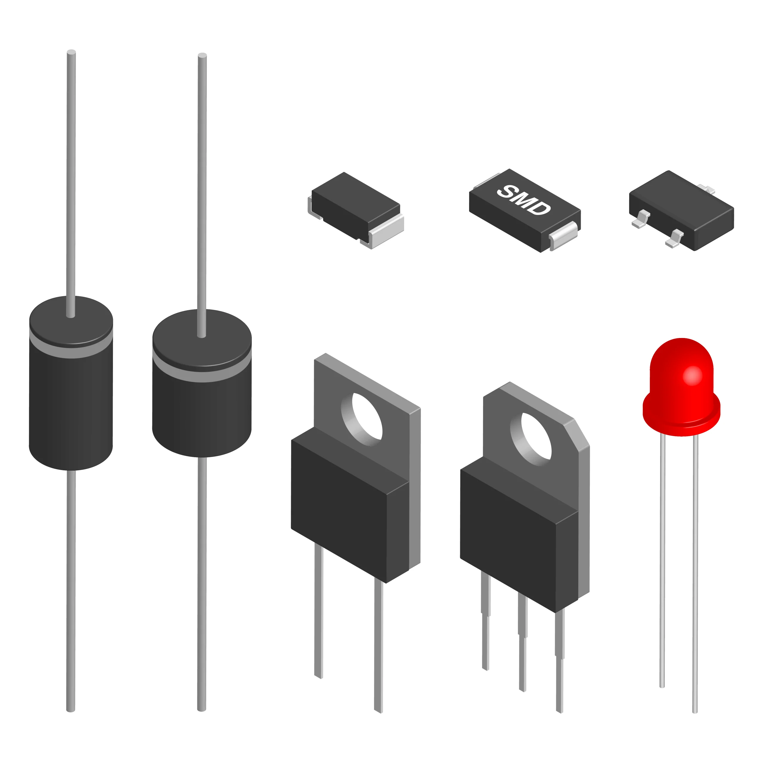
10 tips to choose switches and diodes for your power electronics PCBs
- Ensure the switches (e.g., MOSFETs, IGBTs) and diodes are rated for the maximum voltage and current your circuit will experience. Oversizing components may increase cost, while undersizing them may cause failure.
- Choose switches that are compatible with your circuit’s switching frequency. For high-frequency applications, consider using fast-switching devices like GaN MOSFETs or SiC MOSFETs to reduce switching losses and improve efficiency.
- Select diodes and switches with low conduction losses, such as Schottky diodes and MOSFETs with low Rds(on). This will help reduce heat generation and improve overall system efficiency.
- For applications involving high switching speeds, choose diodes with minimal reverse recovery time (e.g., Schottky diodes or SiC diodes) to reduce switching losses and prevent unwanted power dissipation.
- Pick switches and diodes with appropriate thermal characteristics to handle the heat generated during operation. Ensure proper heatsinking or cooling solutions are in place, especially for high-power components.
- Select diodes with a low forward voltage drop to minimize conduction losses. Schottky diodes typically provide lower forward voltage drops than conventional silicon diodes.
- In demanding environments (e.g., automotive, industrial), opt for diodes and switches with high reliability and ruggedness. SiC and GaN semiconductors offer better performance in harsh conditions compared to traditional silicon devices.
- If your design requires reverse voltage protection, choose diodes like SiC diodes or reverse-blocking devices that can handle high reverse voltages without breakdown.
- When selecting MOSFETs or IGBTs, ensure the gate drive circuit is suitable for the required gate charge, and the driver can handle the switching speeds without introducing excessive losses.
- Some modern switches and diodes come with built-in protection features (e.g., integrated gate drivers or over-voltage protection). Consider these integrated solutions to reduce board complexity and improve system reliability.
7. Opt for low ESR capacitors and low DCR inductors
Capacitors and inductors are pivotal in storing and transferring energy within power electronics circuits. Capacitors and inductors are vital elements for power electronics component selection, especially when considering parameters like ESR, DCR, and ripple current.
| Components | Types | Examples |
|---|---|---|
| Capacitors | Polarized | Electrolytic capacitors |
| Non-polarized | Ceramic capacitors and film capacitors | |
| Inductors | Air-core | Toroids |
| Magnetic-core | E-cores and pot cores |
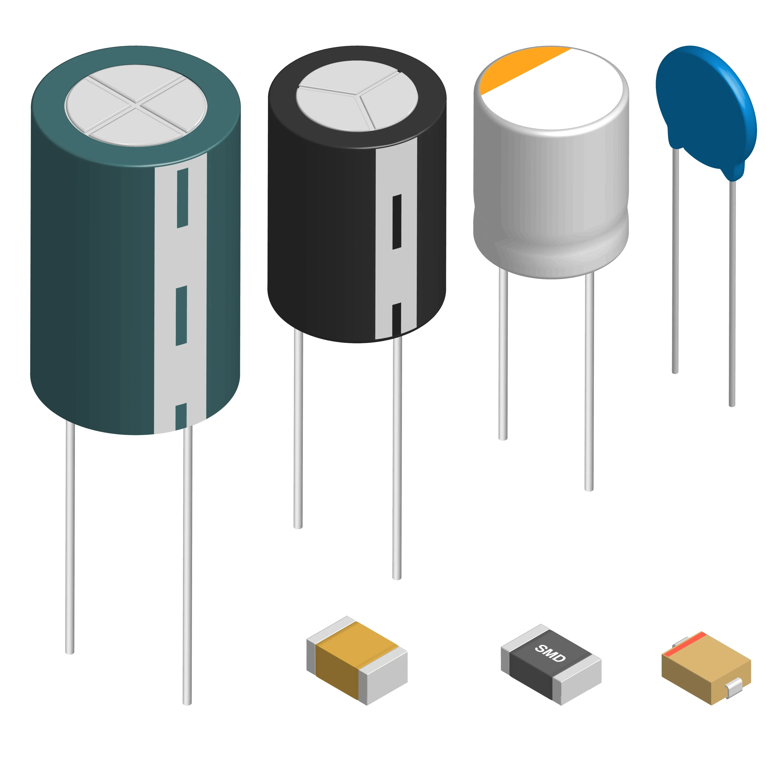
10 guidelines to select capacitors and inductors for power electronics
- Consider parameters like ESR, ESL, ripple current, and voltage ratings, self-resonant frequency, and parasitic capacitance and inductance. Low ESR capacitors are essential for minimizing power losses.
- Always select capacitors with voltage ratings at least 25-30% higher than the maximum voltage they will experience in the circuit to account for voltage spikes and transients.
- Pick ceramic capacitors for filtering high-frequency noise and providing stable performance over a wide range of temperatures.
- Refer to datasheets for ceramic capacitors to understand capacitance derating. This helps avoid unnecessarily over-specifying capacitors, which can lead to increased size and cost.
- For energy storage or smoothing applications, consider electrolytic or tantalum capacitors with higher capacitance values.
- Exercise caution with wet tantalum capacitors, as exceeding recommended voltage ratings, even briefly, can lead to immediate capacitor failure. For a safer alternative, consider using niobium capacitors, which offer better reliability and are less prone to catastrophic failures, such as fires, compared to tantalum.
- Use inductors with low DC resistance (DCR) to minimize power losses, especially in high-current applications.
- Prefer toroid inductors because they offer higher efficiency, lower electromagnetic interference, and compact design due to their circular shape, which reduces energy loss and magnetic field leakage.
- For EM-sensitive applications, choose shielded inductors to reduce radiated noise and prevent crosstalk.
- Aim for a low equivalent series resistance to minimize signal losses in the board.
8. Overrate resistors and fuses to ensure safe operation
Resistors and fuses are essential to safeguard and regulate power electronics circuits.
| Components | Types | Examples |
|---|---|---|
| Resistors | Fixed | Wirewound and metal film resistors |
| Variable | Potentiometers and rheostats | |
| Fuses | Fast-acting | Cartridge and blade fuses |
| Slow-blow | Thermal and resettable fuses |
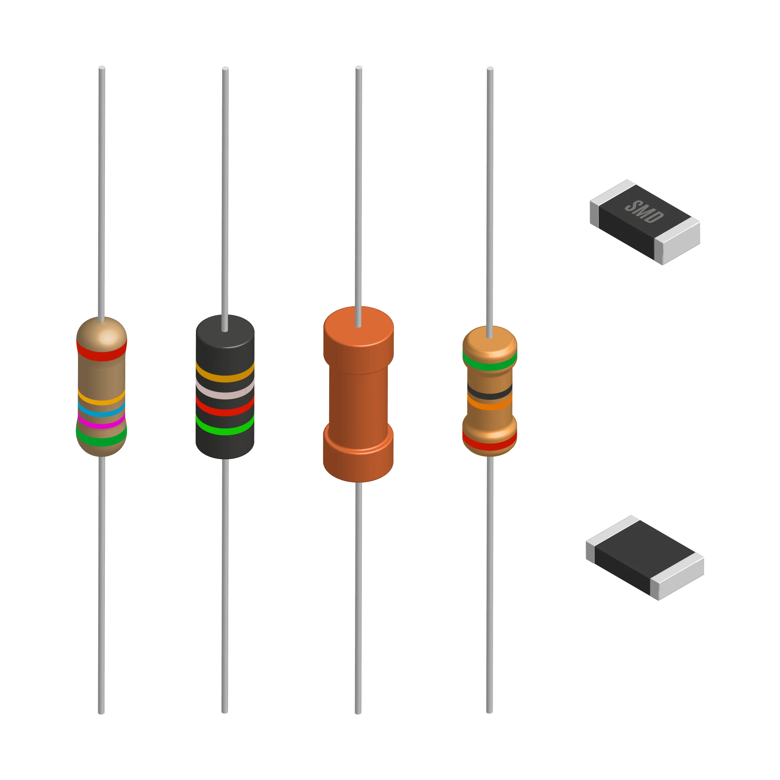
10 strategies to pick resistors and fuses for high-power printed boards
- Ensure the resistor’s power rating is sufficient to handle the expected power dissipation without overheating. Use the formula P=I²R to calculate power dissipation and select a resistor with a higher power rating than the calculated value for safety.
- For stable performance over a wide temperature range, select resistors with a low TCR (temperature coefficient of resistance) to minimize resistance drift.
- Choose resistors with the appropriate tolerance (e.g., 1%, 0.1%) depending on the precision needed in the circuit. Tight tolerances are required for sensitive applications, but may come at a higher cost.
- If space is a concern, surface-mount resistors are a great option as they save board space and can be more efficient in terms of heat dissipation.
- For high-power applications, wire-wound or thick-film resistors are preferred. For high-frequency signals, use metal-film or thin-film resistors to minimize noise and parasitic effects.
- Select resistors with appropriate characteristics based on the function they serve.
- For current sensing, choose precision resistors with a low-temperature coefficient and high stability.
- For voltage dividers, use resistors that will ensure the desired voltage ratios are maintained.
- Snubbers and damping resistors should have higher power ratings to handle voltage spikes effectively.
- Choose fuse types (e.g., time-delay, fast-acting) based on the specific nature of the load.
- Use fast-acting fuses for circuits with low inrush currents.
- Select time-delay fuses for loads with high inrush currents, like motors or transformers.
- Ensure the fuse voltage rating is higher than the maximum operating voltage of the circuit. Overrating resistors and fuses is a safe practice in component selection for power electronics, especially for high-power boards. This prevents the fuse from blowing prematurely or failing to break the circuit in the event of an overcurrent.
- The fuse should have a breaking capacity that can handle the maximum fault current that could occur in the circuit. This is critical to ensure safe operation during short circuits or faults.
- Choose a fuse that fits the physical size constraints of the design and matches the preferred mounting style (e.g., axial, radial, or surface mount).
Make your PCB more efficient by integrating embedded resistors, see how to design a PCB with embedded components.
9. Select isolated sensors and drivers for high-voltage applications
Sensors and drivers are the main components that interface power electronics circuits with external signals and devices.
Sensors monitor critical parameters such as current, voltage, temperature, and position, providing real-time feedback for system control and protection.
Drivers, on the other hand, act as interfaces that translate low-power control signals into high-power actuation, enabling precise and efficient operation of devices like MOSFETs, IGBTs, and other switching components.
| Components | Types | Examples |
|---|---|---|
| Sensors | Passive | Thermistors and shunt resistors |
| Active | Hall-effect sensors and optocouplers | |
| Drivers | Isolated | Gate drivers and transformer drivers |
| Non-isolated | Push-pull drivers and bootstrap drivers |
4 best practices to incorporate sensors and drivers for power electronics interfaces
- Choose passive sensors (e.g., thermistors, shunt resistors) for simpler applications with minimal power requirements, and active sensors (e.g., Hall-effect sensors, optocouplers) for more complex, high-accuracy measurements.
- For high-voltage applications, select isolated sensors and drivers, such as gate drivers with optocouplers or transformer-based drivers, to protect low-voltage circuits from transients.
- Ensure the sensors provide the appropriate signal output for your application (e.g., analog or digital). Incorporate proper signal conditioning circuitry to filter noise and calibrate signals.
- Identify your components’ power demands and choose a suitable power supply. Moreover, appropriate circuitry, such as fuses, varistors, or transient voltage suppressors, must be integrated to ensure the protection of sensitive components.
10. Prefer connectors with secure locking mechanisms
Connectors are the components that connect power electronics circuits, enabling reliable and safe connections for power, signal, and data transmission. Secure locking mechanisms in connectors are a vital part of component selection for power electronics, especially in applications exposed to vibration or mechanical stress.
| Components | Types | Examples |
|---|---|---|
| Connectors | Board-to-board | Headers and sockets |
| Wire-to-board | Terminal blocks and screw terminals | |
| Wire-to-wire | Spade terminals and crimp terminals |
9 guidelines to choose connectors for high-voltage operations
- Choose connectors that can safely handle the maximum current your design will require. Check the manufacturer’s current rating for each connector and consider factors like potential surges or transient currents.
- Gold-plated, silver-plated, or copper contacts can offer improved conductivity and corrosion resistance. Silver is often used in power applications due to its low resistance, while gold is good for low-power or signal applications.
- In power electronics, connectors may be subjected to mechanical stresses, including vibration and movement. Choose connectors with secure locking mechanisms (e.g., screws, latches, or locking pins) to prevent accidental disconnections.
- For applications requiring frequent mating and unmating, select connectors rated for a high number of cycles (e.g., 1000+ mating cycles).
- Ensure that the connector material and insulation can handle the operating temperature range of the board. For power electronics, connectors should typically support higher temperatures (up to 125°C or more) to handle the heat generated during operation.
- The dielectric material must handle the electrical stresses, offering adequate insulation between contacts. Materials like thermoplastics (e.g., PBT or nylon) or ceramics are common.
- If the board is to be used in harsh or outdoor environments, consider connectors with IP-rated sealing (e.g., IP67 or higher) to protect against water, dust, and chemicals.
- In high-frequency applications, opt for shielded connectors to reduce EMI in circuit boards that can affect signal integrity and overall system performance.
- Use power connectors designed specifically for a high current application, such as screw terminal, blade, or heavy-duty press-fit connectors.
It is a good practice to simulate the power supply design you create in your schematic before proceeding to the PCB layout to ensure it will work correctly on the final board.
For more tips on how to select connectors that increase your board’s reliability, see our connector design guide.
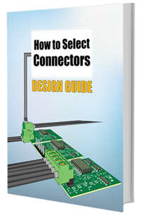
Connector Design Guide
5 Chapters - 32 Pages - 50 Minute ReadWhat's Inside:
- Basics
- Terminology
- Selection and layout rules
- Testing
- Application-specific PCB connectors
Download Now
Emerging technology in power electronics: wide-bandgap semiconductors
Wide-bandgap semiconductors, such as silicon carbide (SiC) and gallium nitride (GaN), have emerged as superior alternatives to traditional silicon-based devices for power electronics. Their wider bandgap (3eV+) allows for high-voltage and high-temperature operations.
They offer high efficiency, smaller size, and better thermal performance, making them ideal for modern applications like electric vehicles (EVs), industrial automation, and renewable energy systems.
- Silicon carbide (SiC): Known for high-voltage applications (1.2kV–6.5kV), SiC devices enable higher power output and are widely used in electric vehicles and industrial equipment.
- Gallium nitride (GaN): Offers high switching frequencies, reduced power loss, and compact size, making it suitable for applications like fast chargers, data centers, and low-power devices. GaN’s high electron mobility and 2D electron gas enable fast switching in power transistors like field-effect transistors (FET) and high-electron-mobility transistors (HEMT).

Both SiC and GaN have excellent thermal properties, ensuring better heat dissipation and higher efficiency in power electronics. The table below compares different semiconductor types:
| Parameters | Silicon (Si) | Silicon carbide (SiC) | Gallium nitride (GaN) |
|---|---|---|---|
| Benefits |
|
|
|
| Applications |
|
|
|
| Cost and performance |
|
|
|
| Adoption barriers |
|
|
|
Despite current limitations, SiC and GaN are gaining traction in niche markets such as EV fast chargers, solar inverters, and data centers. Annual growth rates for GaN devices are expected to increase by 35-75% in the next five years, driven by advancements in fabrication and cost reduction.
For guidelines on building power electronics prototypes, see 7 PCB layout design tips for power electronics.
Key takeaways:
- Evaluate resin content, curing agent, and glass weave style to prevent voiding, conductive anodic filamentation, and electromigration.
- Follow standards like IPC-2152 for thermal design guidance and verify compliance with IEC-60950-1, IPC-2221, and CTI-based test methods.
- Integrate SMPS in heat-sensitive environments to achieve high efficiency and reduce thermal management challenges.
- Use linear power supplies for noise-sensitive, low-power applications with minimal electrical noise, but avoid them in high-power scenarios due to inefficiency and heat generation.
- Use ceramic capacitors for filtering high-frequency noise and stable performance.
- Prefer toroid inductors for lower EMI, higher efficiency, and compact design.
- Use low TCR resistors for stability across temperature ranges.
- Select fuse types (e.g., fast-acting, time-delay) based on inrush current characteristics.
- Choose active sensors like Hall-effect sensors for high-accuracy applications.
- Prefer shielded connectors in high-frequency applications to minimize EMI.
- Select low conduction loss components like Schottky diodes and low Rds(on) MOSFETs to reduce heat and improve efficiency.
- Use GaN for high switching frequencies in applications like fast chargers and low-power devices.
Selecting the right materials and components for power electronics PCBs is critical for achieving a safe and reliable board. From choosing materials with high thermal conductivity and a precise resin-glass balance to advanced component selection like wide-bandgap semiconductors and low-loss diodes, you can create robust power electronics PCBs for high-power applications.
Need help designing a power electronics circuit board? Post your questions on our PCB forum, SierraConnect. Our design experts will resolve them.
About Pooja Mitra : Pooja Mitra is an electronics and communication engineer. With an experience of over three years in the PCB industry, she creates industry-focused articles that help electrical and PCB layout engineers.






Start the discussion at sierraconnect.protoexpress.com