Contents

On-demand webinar
How Good is My Shield? An Introduction to Transfer Impedance and Shielding Effectiveness
by Karen Burnham
After the layout, the design is converted into a standard file format called Gerber files. Most PCB makers use this widely accepted format for manufacturing. Therefore designers need to know how to export gerber and design files in Allegro PCB Editor, the Cadence PCB design software.
Let’s assume that we have completed the PCB design in Allegro. Once our design is ready, we can proceed to generate the artwork files. We will cover the following steps for exporting files and setting rules in this article:
How to export Gerber files in Allegro PCB Editor
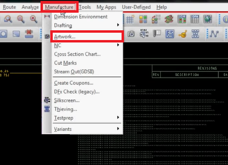
Open your PCB layout in Allegro PCB Editor. To generate a Gerber file, follow these steps:
- Click Manufacture > Artwork
- A window will popup
The popup window: Artwork Control Form.
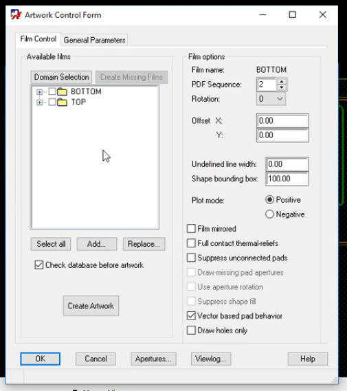
The main purpose of this popup is to select all the required layers in the Available films section. But before that, we have to set the Apertures. For that, follow these steps:
Click the Aperture button > A window will popup
The popup window: Edit Aperture Wheels
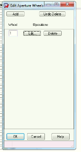
Click Edit > A window will popup
The popup window: Edit Aperture Station
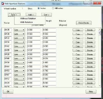
In the Edit Aperture Station window, click Auto > select Without Rotation > click OK.
Once the aperture setting is complete, you will be directed back to the Artwork Control Form popup.
Now, look at the “Available films” column; the only options available will be top and bottom films by default. You can add all the required layers here. Let’s check out how to add layers. For example, here we are adding an outline layer. To do that:
- Right-click on the folder > Add Manual
- A window will popup
- Add layer name in the popup and click OK
- Now a window for subclass selection will popup
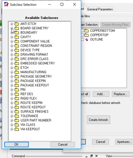
- Select the subclasses from the Board Geometry > select DESIGN_OUTLINE > click OK. Now, the outline layer will appear among the available films.
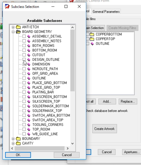
In the same way, you can add N number of layers such as silkscreen top, silkscreen bottom, solder mask top, and bottom, etc.
Required settings in the popup window
- Set a parameter in “Undefined line width” for all films
- Next, click the General parameter tab on the top
- Choose Device type, inches as Output unit, Film size limits, Format values, Error action, etc. Choose all the required settings in the general parameters tab and go back to the Film control page
Now click ‘Select all’ > then click ‘Create Artwork’
A notification will appear on the bottom left corner about the saved artwork.
To view your generated Gerber, click Viewing.
IPC-2581 is becoming popular with designers due to its provision for a unified design data format. To get more insights, read how to export and get started with IPC-2581.
How to export NC drill files in Allegro PCB Editor
- Go to Manufacture > NC > NC drill
- A window will popup
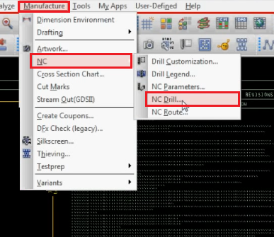
Set the parameters in this popup window: NC Drill
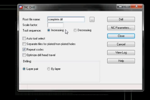
Required settings in the popup window
- Choose a Root file name
- Check Auto tool select
- Uncheck Repeat codes
- Check Optimize drill head travel
- Check Increasing from tool sequence options
- Check Layer pair from drilling option
- After all the settings are done, we need to set the NC parameters. To do that:
Click NC parameters from the above window > A new popup window will appear
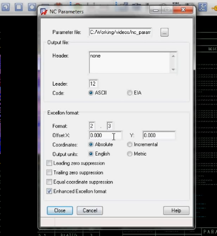
Required settings in the NC parameters window
- Make sure Leading zero suppression & Enhanced Excellon Format are checked
- Select ASCII as code
- Choose all other settings as per your requirements
Once you have done all the required settings in the NC parameters, click Close.
This will lead you back to the NC Drill window with the Drill button. Click on Drill.
The drill files will be generated in the selected root location.
Read about the future of Gerber files: IPC-2581 Set to Retire Gerber Files Across the Board
IPC Class 3 Design Guide
8 Chapters - 23 Pages - 35 Minute ReadWhat's Inside:
- IPC guidelines for manufacturing defects
- IPC standards for assembly processes
- Common differences between the classes
- IPC documents to set the level of acceptance criteria
Download Now
How to export Netlist in Allegro PCB Editor
To export the netlist, open the schematic of your design. Select the .dsn file from the project files for which you need to generate the netlist file. Now, follow these steps:
- Click Tools > Create Netlist
- A window will popup
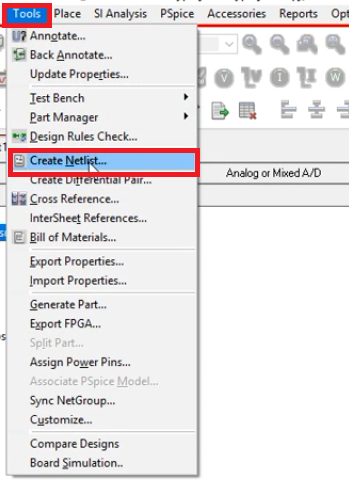
The popup window: Create Netlist
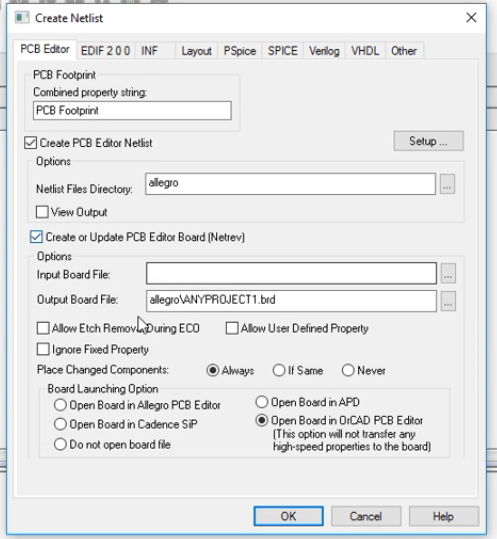
Required settings in the popup window:
- Combined property string should be PDF Footprint
- Select the Output directory from Netlist Files Directory, where you want to save the file
- Check “Create PCB Editor Netlist”
- Check the “Create or update PCB Editor Board”
- Name your netlist file in the Output Board File
- Choose a Board launching Option. If you don’t have the license for Allegro PCB Editor, then check Open Board in OrCAD PCB Editor
Now click OK to save your netlist file.
Also read, How to Export Gerber and Production Files in Altium Designer
How to export BOM in Allegro PCB Editor
Before generating the BOM, we need to check whether we have added all the information for each of the components in the schematic. For that, type ctrl+A then ctrl+E. Now you can see all the information about the components. Make sure you have added all the details. Once this is done, we are ready to export BOM.
To export BOM, follow these steps:
- Select your design file that ends with .dsn > Tools > Bill of Material
- A window will popup
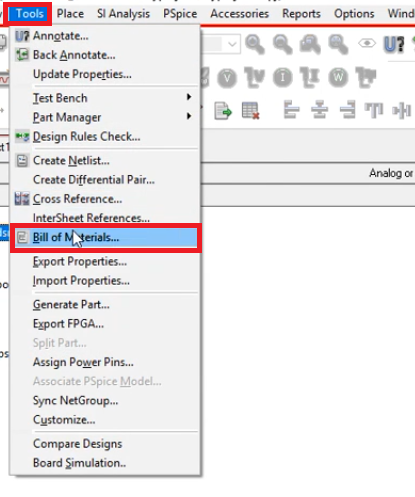
The popup window: Bill of Materials
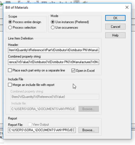
Required settings in the popup window
- Add the Headers and Combined property string.
- Check Open in Excel
- Select the Output directory where you want to save the file
Now click OK to save your BOM file.
How to export PDF in Allegro PCB Editor
We must generate a PDF for schematic and layout design. First, we are going to generate a PDF of the schematic. To do that, follow these steps :
Open the schematics.
- File > Export > PDF
- A window will popup
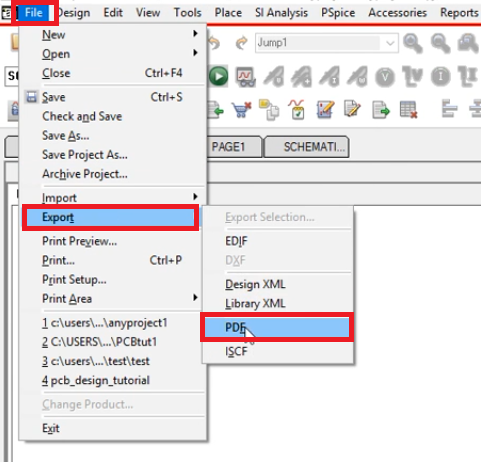
The pop window: PDF export
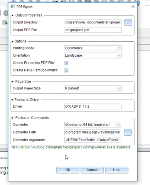
Required settings in the popup window
- Select the Output directory where you want to save the file
- Retain all other settings as default.
- We need a converter to generate a PDF file. Here we have the Ghostscript converter installed. If you haven’t installed Ghostscript, you have a link at the bottom of the popup. You can install the Ghostscript from the link.
Now click OK. Your file will be generated at the selected location.
Also read: How to Export Gerber and Other Production Files in KiCad
Generate PDF for layout design
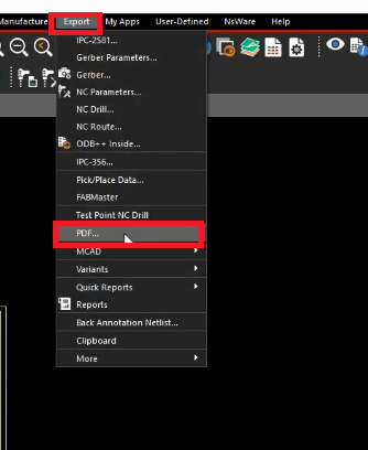
- Go to Export > PDF
- A window will popup
The popup window: PDF export
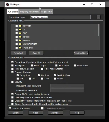
If you have already created the Gerber files, you can see your previously created films in the ‘Available Films’ column.
Required settings in the popup window
- Name the file in the Output File Name section
- Check the Output PDF in black and white mode only if you prefer to generate the PDF file in B&W.
- To encrypt the PDF, select security and set a password for your file.
- Also, set Property parameter and Page setup.
Then click Export to generate the file.
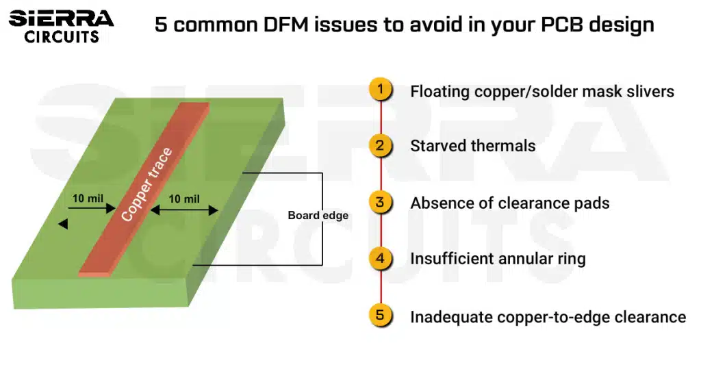
This is how we export Gerber and other files in Allegro that is required by the PCB manufacturers. After the files have been generated, verify them, and send them to your manufacturer. It is also important to examine and address the common issues related to Gerber files like incorrect drill file format, absence of fab drawing, missing board outlines, etc. You can avoid such problems with the help of sophisticated tools like CAD and DFM.

Design for Manufacturing Handbook
10 Chapters - 40 Pages - 45 Minute ReadWhat's Inside:
- Annular rings: avoid drill breakouts
- Vias: optimize your design
- Trace width and space: follow the best practices
- Solder mask and silkscreen: get the must-knows
Download Now


