


Contents

On-demand webinar
How Good is My Shield? An Introduction to Transfer Impedance and Shielding Effectiveness
by Karen Burnham
Designing flex PCBs for high-temperature (>125°C) applications presents challenges like thermal stress and trace delamination. You can overcome these issues by selecting materials with compatible CTEs and using reinforcing elements like stiffeners.
In this article, you will learn 6 common challenges in building heat-resistant flex PCBs and ways to overcome them.
Highlights:
- Use thermally conductive adhesives and consider adhesiveless laminates.
- Choose dielectric materials with high-temperature stability.
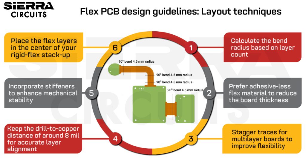
- Maintain proper bend radius, stagger traces, use cross-hatched ground planes, and incorporate stiffeners wherever necessary.
- Perform thermal shock, burn-in, and mechanical stress tests to validate flex PCB performance under extreme conditions.
A quick guide for selecting high-temperature flex materials
FPCs are typically made up of flex cores, copper films, coverlays, and adhesives to bond these together. Some designs may also include stiffeners for component support and pressure-sensitive adhesive (PSA) for attachment.
All standard flex materials can withstand temperatures from -40 °C to 85 °C. For high temperatures exceeding 85 °C, specialized materials and construction methods are necessary. The table below serves as a guide to select flexible circuit materials for high temperature applications:
| Component | Material | Continuous operating temperature | Key benefits |
|---|---|---|---|
| Core materials | Polyimide (PI) | –269°C to +200°C (short term up to 400 °C) | High durability, chemical resistance, low CTE |
| LCP (liquid crystal polymer) | Up to 250°C | Low moisture absorption, great for RF/high-speed | |
| PEN (polyethylene naphthalate) | Up to 150°C | Good heat resistance and dimensional stability | |
| Polyester (PET) | Up to 150°C | Cost-effective but lower thermal resistance | |
| Copper type | Rolled annealed (RA) copper | High melting point, 1,984°C, but prolonged high temperatures exposure can cause copper to undergo structural changes. | Lower CTE, better suitable for Dynamic flexing, reduces stress |
| Electrodeposited (ED) copper | – | Cheaper, but more prone to cracking | |
| Coverlay | Acrylic | 85°C | Flexible, general-purpose. |
| Epoxy | 140°C | Strong bond, chemical resistance. | |
| Polyimide | Up to 200°C | High thermal stability, protects circuits, minimal outgassing. | |
| Adhesives | Acrylic-based | Up to 85°C | General-purpose, cost-effective |
| Epoxy-based | Up to 140°C | Good for medical applications | |
| Polyimide-based | Up to 200°C | Best for extreme temperatures | |
| Stiffeners | FR4, polyimide | 135/200°C | Adds structural support, prevents warping |
| Solder | Lead-free SAC alloy | 217-227°C (melting point) | High reliability, meets RoHS compliance |
| Surface finish | ENEPIG | Up to 150°C | Prevents oxidation, improves solderability |
Download our design guide to learn how to pick the right materials for your PCBs.

PCB Material Design Guide
9 Chapters - 30 Pages - 40 Minute ReadWhat's Inside:
- Basic properties of the dielectric material to be considered
- Signal loss in PCB substrates
- Copper foil selection
- Key considerations for choosing PCB materials
Download Now
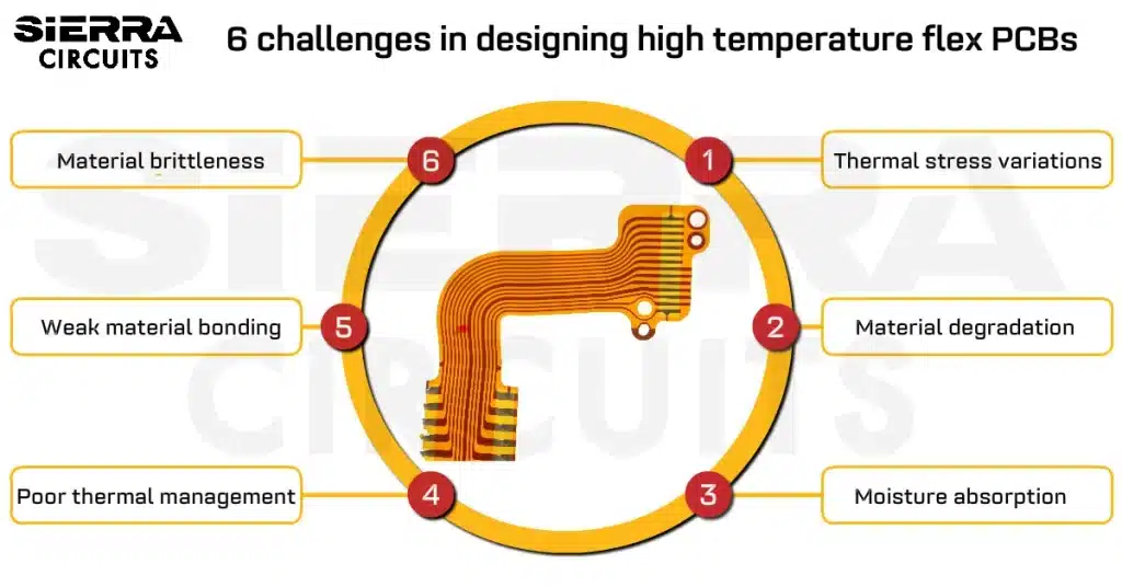
6 challenges in designing high-temperature flex PCBs
1. FPCs undergo thermal stress due to temperature variations
Different materials in FPCs (flexible printed circuits), like copper, dielectric layers, and adhesives, expand and contract at different rates. This CTE mismatch creates significant stress, which can lead to layer delamination and solder joint failures.
Furthermore, flex materials are repeatedly exposed to both high and low temperatures. This accelerates material degradation and fatigue, leading to premature failure.
Consider these guidelines to overcome this challenge:
8 ways to mitigate the effects of thermal stress
- Select materials with closely matched CTEs to minimize stress. Polyimide PCB materials are suitable for high-temperature flex and rigid-flex boards, as they feature excellent thermal stability.
- High thermal stress can compromise via integrity in flex PCBs. Use filled or capped vias for improved mechanical strength and thermal conductivity. Incorporate teardrop-shaped via pads to reduce stress concentration due to thermal expansion at via-to-trace junctions.
- Conduct thermal cycling tests to evaluate the flex circuit’s performance under realistic operating conditions. This helps you identify and address potential failure points early in the design phase.
- Maintain controlled impedance in high-speed flex circuits and simulate performance over the operating temperature range to prevent signal degradation.
- Position copper layers closer to the neutral bend axis to reduce tensile and compressive stress during flexing, while integrating relief cuts for enhanced flexibility. Maintain a symmetrical stack-up around the neutral axis to evenly distribute thermal expansion and minimize warping.

- Follow IPC-2223 bend radius guidelines (e.g., 10x material thickness for single-layer, 20x for multi-layer in non-dynamic applications) to prevent copper fatigue and cracking under thermal cycling.
- Avoid vias in flex sections of dynamic boards to prevent cracking under repeated flexing and high temperatures, and design pads with sufficient annular rings (e.g., 2 mil) for mechanical support and to prevent solder joint failures.
- Consult your manufacturer early to address DFM requirements specific to high-temperature flex boards, ensuring thermal stress resilience.
2. Material degradation increases the dielectric loss
Elevated temperatures can degrade the dielectric properties of flex board materials. This reduces the insulation resistance (the ability of the dielectric to withstand voltage and prevent current leakage), increases dielectric losses (energy dissipated as heat within the dielectric material), and weakens the adhesive bonds between layers, compromising the structural integrity of the flex board.
9 strategies to minimize material degradation in flex boards
- Choose dielectric materials with high-temperature stability (polyimide can endure temperatures up to 200°C).
-
Opt for all-polyimide constructions (clads, bondplies, and coverlays) to maximize service temperature performance and minimize degradation.
- Increase the thickness of the copper to enhance the heat dissipation.
- Use adhesives specifically designed to withstand high-temperature ranges. These adhesives maintain their bonding strength and integrity even under elevated thermal conditions.
- Consider using polyimide and epoxy based adhesives, as they offer excellent thermal stability and resistance to degradation.
- Use thermal interface materials (TIMs) to transfer heat away from critical areas, preventing excessive heat buildup in the adhesive layers.”
- Conduct accelerated thermal aging tests to evaluate long-term material performance under sustained heat exposure.
- At high frequencies (e.g., 5G applications), dielectric loss increases more significantly with temperature. Use low-loss tangent materials like LCP (around 0.002-0.004 at 1 MHz) for RF flex circuits.
- Choose low-outgassing adhesive materials like epoxies, silicones, and polymers, to prevent volatile release that degrades dielectric properties and structural integrity.
- Select heat-resistant materials with high creep resistance to combat permanent deformation and stress relaxation at high temperatures, designing to minimize stress concentrations.
Download our eBook to learn how to design a reliable flex PCB.

Flex PCB Design Guide
10 Chapters - 39 Pages - 45 Minute ReadWhat's Inside:
- Calculating the bend radius
- Annular ring and via specifications
- Build your flex stack-up
- Controlled impedance for flex
- The fab and drawing requirements
Download Now
3. Moisture absorption leads to short circuits and leakage current
High-temperature environments can accelerate moisture absorption in the flex boards. This can lead to short circuits, increased leakage currents, and reduced insulation resistance, compromising electrical performance. Moisture affects conductivity and dielectric properties by providing an undesired pathway for current leakage and altering the material’s dielectric constant.
IPC-1601 A standard provides guidelines for effective moisture management in flexible circuit boards. Follow these guidelines to reduce moisture in your flex boards.
9 best practices to prevent moisture absorption in high-temperature flex PCBs
- Use materials with low moisture absorption properties, such as polyimide (0.5%) or other high-performance polymers.
- Ask your CM to seal the edges of the board to minimize exposed areas where moisture can enter.
- Ensure that conductive traces and pads are well-protected and not left exposed, as they can act as pathways for moisture.
- Apply conformal coatings (e.g., perylene, silicone, or acrylic) to create a barrier that prevents moisture from hampering the copper features.
- Make sure your boards are stored in a controlled, low-humidity environment. Consider the components’ moisture sensitivity level (MSL) rating defined by IPC J-STD-033 or IPC J-STD-020, as shown in the table below. It specifies how long a board can be exposed to ambient conditions before it needs re-baking or dry packaging to eliminate absorbed moisture.
| MSL level | Floor life before the board needs re-baking | Storage temperature/Humidity | Dry packing requirement |
|---|---|---|---|
| MSL 1 | Unlimited | ≤30°C/85% RH | No |
| MSL 2 | One year | ≤30°C/60% RH | Yes |
| MSL 2a | 4 weeks | ≤30°C/60% RH | Yes |
| MSL 3 | 168 hours | ≤30°C/60% RH | Yes |
| MSL 4 | 72 hours | ≤30°C/60% RH | Yes |
| MSL 5 | 48 hours | ≤30°C/60% RH | Yes |
| MSL 5a | 24 hours | ≤30°C/60% RH | Yes |
| MSL 6 | Mandatory bake before use | N/A | Yes |
- Utilize desiccant packets when you store and ship your boards.
- Ensure raw materials are stored in dry, controlled environments and handled with gloves to avoid humidity absorption.
- Include a humidity indicator card (HIC) for moisture-sensitive components. They track internal humidity and signal high moisture levels.
- Implement a bake-out process before assembly to remove any absorbed moisture from the flex board materials.
- Apply fluoropolymer coatings (e.g., PTFE) to repel moisture without compromising flexibility.
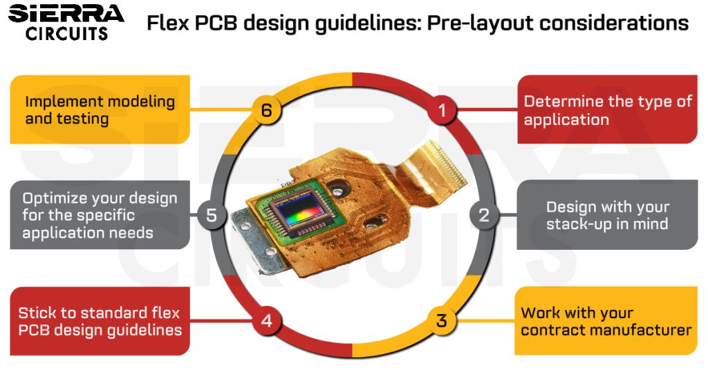
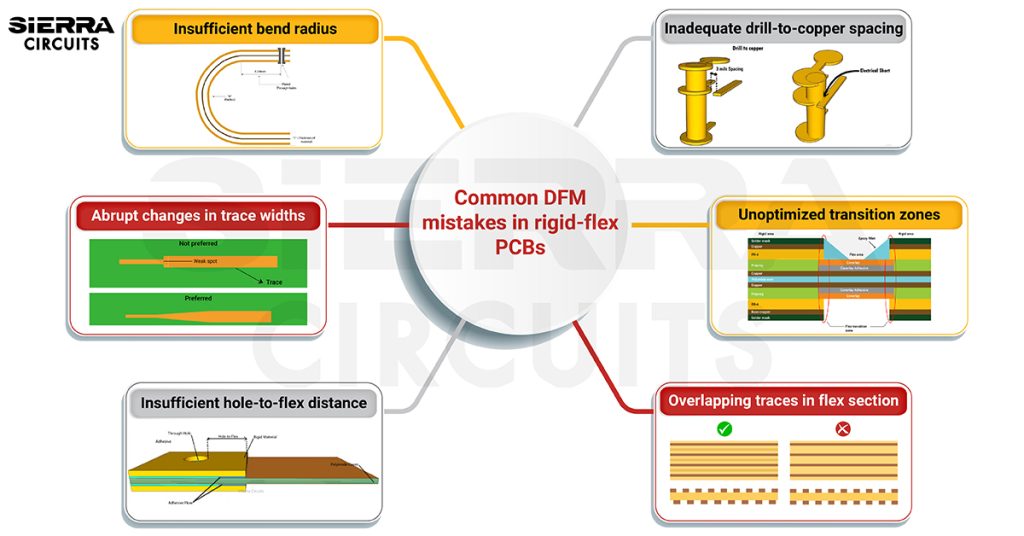
For expert tips on flex PCB design, read our articles: flex PCB design guidelines part 1: pre-layout considerations and flex PCB design guidelines part 2: optimizing layout for manufacturing.
4. Poor thermal management leads to excessive heat build-up
High temperatures in flex boards can lead to component failure, increased circuit resistance, and structural issues like delamination. As a PCB designer, you need to incorporate the best thermal management strategies to prevent overheating.
16 techniques to increase heat dissipation in FPCs
- Use high-temperature-rated adhesives, such as polyimide-based adhesives, that can withstand up to 220°C, although they require specialized lamination equipment and are more expensive. Avoid acrylic-based adhesives rated at 80-90°C for high-temperature applications.
- Increase the surface area as much as possible to improve the surface-to-volume ratio.
- Use thinner core and coverlay materials (e.g., 0.5 mil) to improve heat dissipation capabilities.
- For high-temperature rigid-flex PCBs, incorporate aluminum heat sinks, which are more thermally conductive than stainless steel, to dissipate heat efficiently.
- Add localized selective copper planes on external or internal layers to distribute heat throughout the flex circuit.
- Use thermally conductive pressure sensitive adhesives (PSAs) to attach the flex circuit to the metal enclosure of the final assembly, effectively using the enclosure as a heat sink.
- Ensure that the flex circuit operates within the maximum continuous operating temperature of the adhesives and other materials to prevent breakdown and delamination.
- Incorporate heat pipes or heat spreaders made up of highly thermally conductive materials like aluminum or graphite to the flex circuit board surface through lamination to provide an additional layer of thermal management.
- Incorporate thermal vias to facilitate effective heat transfer. Consider the specific requirements for flexibility and ensure the chosen via structure (e.g., filled vias) and materials can withstand the mechanical stresses of bending and flexing. Connect thermal vias to internal copper planes or heat spreaders for optimal heat dissipation.
- When using a vented enclosure, allocate enough space to allow for sufficient natural convection. For non-vented enclosures, consider radiative heat transfer; specify the emissivity of the flex circuit and the enclosure.
- Use thermal simulation tools to analyze the thermal performance of the flex circuit design and identify potential hot spots. This allows for design adjustments before fabrication.
- Minimize the distance between heat-generating components and heat sinks, and avoid clustering heat-sensitive components near high-power devices to optimize heat dissipation.
- Optimize trace width and spacing to handle high currents and reduce resistance, using wider traces to enhance heat dissipation and reliability.
- Balance layer count wisely, using multi-layer designs with ground planes for better heat dissipation while ensuring flexibility isn’t overly compromised.
- Incorporate thermal shielding materials like Kevlar, titanium, or high-temperature plastics (PTFE) for heat insulation and mechanical protection.
- Use solid or cross-hatched copper or conductive silver layers for EMI shielding in flex PCBs.

5. High temperatures weaken the bond between copper and dielectric material
Prolonged exposure to heat can reduce the strength of the bonding between the copper traces and dielectric material. This can lead to delamination and open circuits.
7 tips to ensure reliable adhesion in flex printed boards
- Use adhesives with high thermal stability, such as polyimide or epoxy-based adhesives rated for high temperatures.
- Consider adhesiveless laminates (copper directly bonded to polyimide) to eliminate the adhesive layer entirely.
- Ensure proper surface preparation (cleaning and roughening) to enhance adhesion.
- Make sure your CM employs controlled lamination processes for bonding layers together. Precise temperature and pressure control are critical.
- Consider using plasma etching to enhance the surface roughness of the dielectric before copper lamination, improving adhesion.
- When applying coverlay, group pads in tight spaces to avoid individual openings, ensuring reliable coverage and adhesion.

- Avoid thermoset adhesives, which become brittle at high temperatures, and opt instead for thermally stable options like polyimide or epoxy.
6. Dielectric layers and copper can become brittle over time
Polyimide and other dielectric materials can become brittle when exposed to high temperatures over time. This is due to the breakdown of polymer chains and the loss of plasticizers that maintain flexibility. At very high temperatures (typically above 200°C), copper and other conductive metals can undergo grain growth (increase in the size of crystal grains) and oxidation, leading to embrittlement.
6 tips to prevent copper and dielectric brittleness in flex PCBs
- Use rolled annealed copper instead of electrodeposited copper. The annealing process relieves internal stresses in copper traces, reducing the risk of cracking.

- Use the right copper thickness: For flex PCBs, choose between 0.25 oz (9 µm) and 2 oz (70 µm) to balance flexibility and durability.
- Increase the thickness of copper traces to improve durability and reduce the risk of cracking.
- Apply protective coatings, such as immersion silver or gold, to prevent oxidation and enhance thermal performance, thereby extending the lifespan of the metal traces.
- Avoid excessive bending or mechanical stress in high-temperature operating environments to prevent cracking.
- Design copper traces with rounded corners and smooth transitions to minimize stress concentrations that can lead to cracking.
- Incorporate stiffeners (e.g., FR4, polyimide, or polyester) to support connector and component areas, reducing mechanical stress and brittleness.

Sierra Circuits manufactures flex PCBs that withstand extreme bending and deformation, enduring up to 200,000 cycles. Visit our flex PCB manufacturing capabilities to learn more.
Advanced testing methods for high-temperature flex PCBs
While features like thermal vias, heat sinks, and extra copper can help manage heat, they may not fully protect against thermal shock, which can cause catastrophic failures. To address this, high-temperature flex PCBs must undergo specialized testing to validate their performance under extreme conditions.
1. Thermal shock test
This test evaluates a PCB’s ability to withstand rapid temperature changes. This process involves exposing the board to high temperatures for a short duration before inspecting it for damage. Effective thermal management designs can help mitigate risks associated with thermal shock, especially for applications in rugged environments.
Standards related to thermal shock testing:
- IPC-TM-650 2.6.7: Specifies thermal shock testing over a range of temperatures, typically from -55°C to the substrate’s glass transition temperature (Tg) or up to 210°C.
- MIL-STD-202G: Defines thermal shock testing methods for military and aerospace applications, using air-to-air or liquid-to-liquid transfers to simulate rapid temperature changes.
By conducting this test, you can identify the following issues
- Thermo-mechanical stress: Rapid heating can cause conductors or mechanical components to fail.
- Thermal fatigue: Repeated temperature fluctuations can lead to fatigue, micro-cracking, or embrittlement of materials over time.
- Component failure: Individual components may fail even if the board itself survives, depending on their thermal tolerance.
- Solder fracture: Tensile and shear stress in solder balls can lead to fractures, especially at brittle interfaces between dissimilar metals.
- Via fracture: Stress concentration in vias depends on their aspect ratio and geometry (through-hole vs. blind vias).
- Delamination: Extreme deformation can cause conductors and substrates to separate.
This test validates a flex PCB’s ability to endure rapid temperature fluctuations without developing cracks, delamination, or solder joint failures.
2. Burn-in testing
This test involves electrically or thermally stressing flex boards to analyze their performance over an extended period (40-160 hours) at high temperatures (up to 125 °C). There are two primary types of burn-in testing:
- Dynamic testing: The board is subjected to high temperatures while input signals are applied to all components. This method helps identify potential failure points and is typically used for complex PCB designs in industries such as aerospace and defense.
- Static testing: This method applies high voltage and temperature without input signals, focusing on the board’s resilience when stored at elevated temperatures over time. Static testing is generally less expensive and simpler than dynamic testing.
3. Mechanical stress tests
Flex PCBs undergo additional tests to evaluate their durability under bending, vibration, and thermal cycling.
- Bending test: These tests assess the flex circuit’s ability to endure repeated bending cycles without cracking or delaminating.

- Vibration test: This test simulates the effects of vibration and shock that the flex circuit may experience during transportation, handling, or operation. It ensures that the circuit can withstand these stresses without failures such as cracks, delamination, or component detachment.
- Pull test: These tests evaluate the strength of solder joints and the adhesion of components to the PCB. They involve applying a controlled force to the components to assess their resistance to detachment.
In addition to these tests, visual inspections and electrical performance tests are also conducted to assess the overall integrity of the flex circuit after undergoing mechanical stress.
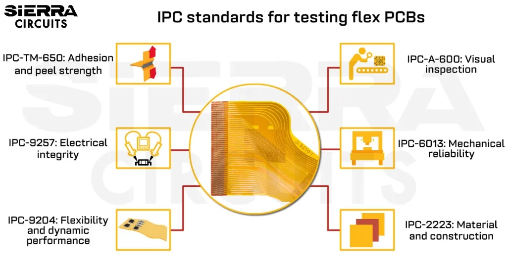
4. IPC-TM-650 2.6.21B test
IPC-TM-650 2.6.21B test method evaluates the service temperature of metal-clad flexible laminates, cover materials, and adhesive bonding films. This test method assesses key properties such as peel strength and dielectric strength after thermal aging, ensuring that the materials can withstand extreme operating conditions.

This test method ensures that flex PCB materials can withstand prolonged exposure to high temperatures without significant performance degradation. The IPC-TM-650 2.6.21B test method provides valuable data on peel strength and dielectric strength retention, which can guide decisions on material thickness, conductor width, and thermal management strategies.
5. IPC 6013 testing requirements for flex PCBs
IPC-6013 standard serves as the foundation for testing and performance specifications for flex PCBs. It outlines over 23 test methods for raw materials and finished products. It provides detailed performance criteria and testing requirements to ensure the reliability of flex PCBs in various applications, including high-temperature environments.
The table below summarizes the flex PCB tests defined by IPC-6013:
| Test category | Test name | Purpose |
|---|---|---|
| Visual and microscopic inspection | Surface defects | Inspect for cracks, delamination, or surface defects that could compromise performance. |
| Microsection analysis | Examines cross-sections to verify layer alignment, via quality, and material integrity. | |
| Electrical testing | Continuity and isolation | Ensures conductive traces are properly connected and isolated per the design. |
| Insulation resistance | Measures resistance between conductors to prevent leakage currents, especially at high temperatures. | |
| Dielectric withstanding voltage (DWV) | Tests the board’s ability to endure high voltages without breakdown. | |
| Mechanical testing | Flexibility and bend testing | Evaluates the board’s resistance to bending and flexing without failure. |
| Peel strength | Measures the adhesion strength of copper traces to the dielectric material. | |
| Dimensional stability | Checks for changes in board dimensions after high-temperature exposure. | |
| Environmental testing | Thermal shock testing | Assesses the board’s ability to handle rapid temperature changes (-55°C to 125°C or higher). |
| Thermal cycling | Evaluates performance under repeated temperature fluctuations. | |
| Humidity exposure | Simulates high-humidity conditions (e.g., 95% RH) to check for moisture-induced failures. | |
| Condensation testing | Exposes the board to temperature shifts causing condensation to test moisture resistance. |
For common queries and answers about flex PCB design and manufacturing, check FAQs for manufacturing flex PCB.
Key takeaways:
- Select high-temperature materials like polyimide (PI) for core materials, which can withstand temperatures up to 260°C for short-term exposure.
- Implement strategic stress relief cuts to allow flex circuits to accommodate differential expansion.
- Choose appropriate surface finishes ( ENIG and OSP) to prevent oxidation at high temperatures.
- Incorporate thermal management techniques such as copper planes, thermal vias, and heat sinks.
- Apply conformal coatings to provide moisture barriers in high-temperature environments.
- Utilize cross-hatched ground and power planes to increase flexibility and reduce thermal expansion stress.
- Conduct rigorous testing including thermal shock, burn-in, and mechanical stress tests.
- Adhere to IPC standards like IPC-TM-650 2.6.21B and IPC-6013 for proper testing and validation.
Designing flex PCBs for high-temperature applications requires careful material selection, strategic layout planning, and robust thermal management techniques. By addressing challenges such as thermal stress, material degradation, moisture absorption, and adhesion loss, you can create FPCs that perform reliably even under demanding thermal conditions and enhance their reliability and longevity.
Have questions on designing flex PCBs for high-temperature applications? Post your queries on SierraConnect. Our PCB experts will answer them.


Start the discussion at sierraconnect.protoexpress.com