Contents

On-demand webinar
How Good is My Shield? An Introduction to Transfer Impedance and Shielding Effectiveness
by Karen Burnham
Humanoid robotics PCB assembly requires advanced techniques like AI-driven component placement and 3D circuit integration. These methods ensure strong solder joints and efficient thermal management.
As a robotics engineer, understanding these key aspects will help you select the right contract manufacturer capable of assembling high-performance printed boards.
In this article, you will learn the cutting-edge assembly techniques and essential components needed to assemble your robotics circuit boards.
Highlights:
For a reliable robotic PCBA:
- Select a manufacturer that employs advanced soldering techniques, such as vapor phase soldering and laser soldering.
- Choose the right board architecture (centralized, distributed, or hybrid) to enable effective communication between microcontrollers, sensors, actuators, and power management systems.
- Ensure stable power distribution with voltage regulators, DC-DC converters, and battery management systems.
- Implement efficient motor control systems using motor driver ICs, MOSFETs, and gate drivers to ensure precise limb movement and actuation.
- Use high-speed connectors like micro coaxial, FPC/FFC, and high-power motor connectors for high-speed data or power transmission across critical components.
To learn more about design and fab, see humanoid robotics PCB design and advanced manufacturing techniques.
What is humanoid robotics?
It is a branch of robotics that focuses on designing, building, and programming bots that resemble and mimic human form and behavior.
These robots possess human-like features, including arms, legs, and expressive faces, enabling them to perform a wide range of tasks, from assisting in healthcare and customer service to conducting advanced research in artificial intelligence and biomechanics.
Some well-known humanoids are Honda’s ASIMO, Boston Dynamics’ Atlas, and Tesla’s Optimus.
What are the advanced PCB assembly techniques for humanoid robotics?
We have listed 3 advanced circuit board assembly capabilities required for robotics. Ensure your manufacturer meets these requirements.
1. Cutting-edge soldering techniques for long-lasting connections
To ensure durability, advanced soldering methods are employed to prevent damage to sensitive electronic components and maintain precision in high-density circuit layouts.
Vapor phase soldering (VPS) and selective soldering for thermal stability
VPS uses the condensation heat of a vaporized liquid to achieve uniform heating of electronic components and PCBs.
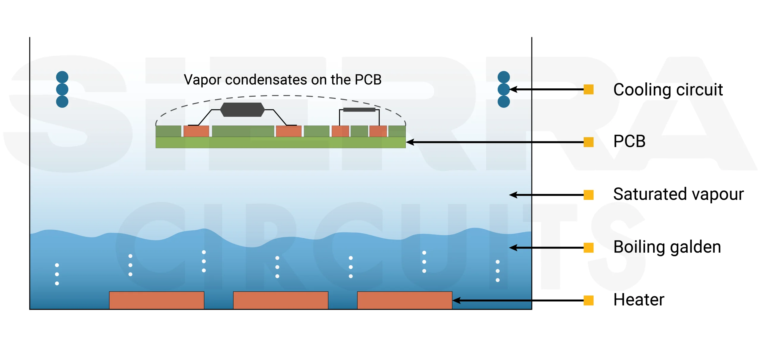
Advantages:
- This technique is particularly effective for humanoid robotics over traditional reflow soldering as it minimizes thermal stress on delicate sensors, AI processors, and micro-actuators.
- It prevents overheating or cold joints, maintaining the signal integrity.
In addition to VPS, selective soldering is also a suitable technique. It is a process used to solder specific components on a PCB by applying molten solder only to targeted areas, ensuring precision and minimizing heat exposure to surrounding parts.
This method is ideal for mixed-technology boards (combining through-hole and surface-mount components), which are common in robots due to their hybrid mechanical and electronic systems.
Laser soldering for high-precision and miniaturized connections
It is a non-contact soldering technique that uses a focused laser beam to heat and melt solder, enabling accurate and controlled electronic component connections.
Benefits:
- Laser soldering is increasingly used for ultra-fine joints in flexible and rigid-flex PCBs, which are essential for robotic limbs and joints requiring high dexterity.
- This method is also beneficial for repairing or reworking delicate components without damaging surrounding areas.
This technique is used in micro-actuators, wearable sensors, and fine-wiring applications within humanoid limbs and fingers.
Download our eBook to learn how to design a reliable flex PCB.

Flex PCB Design Guide
10 Chapters - 39 Pages - 45 Minute ReadWhat's Inside:
- Calculating the bend radius
- Annular ring and via specifications
- Build your flex stack-up
- Controlled impedance for flex
- The fab and drawing requirements
Download Now
2. AI-driven pick-and-place systems for micron-level accuracy
High-speed memory modules (e.g., DDR5), AI processors, and advanced LiDAR sensors demand precise placement to maintain signal integrity. Misalignment can cause signal interference, reducing processing efficiency.
Robotic-assisted surface-mount technology (SMT) ensures micron-level accuracy in component placement for humanoid robotics PCB assembly.

This method provides the following advantages:
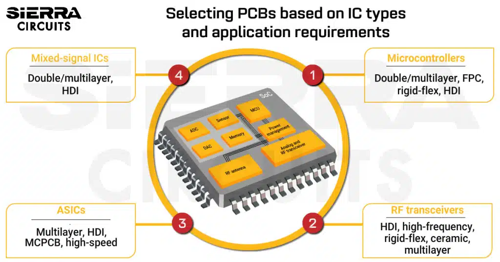
- It is ideal for assembling fine-pitch components like ball grid arrays (BGAs), field-programmable gate arrays (FPGAs), and high-speed integrated circuits. To select the right board type for such microchips, see how to choose the right PCBs for IC integration.
- These systems can also adapt to variations in component sizes and shapes, which is critical for custom or proprietary components used in robots.
Sierra Circuits’ surface mount technology (SMT) assembly service provides high-precision component placement, from standard resistors to advanced BGA assemblies, ensuring excellent performance. Check our PCB assembly capabilities to learn more.
3. 3D component placement for compact, high-density circuitry
Humanoid robotics often requires custom-shaped boards to fit within compact, anatomically inspired structures.
Unlike conventional flat, planar PCBs used in most electronic devices, these circuit boards often employ three-dimensional (stacked) designs to optimize space without affecting their functionality.
3D component placement offers the following advantages:
- Stacking allows for better spatial efficiency in compact robotic structures, reducing the footprint while maintaining functionality.
- Techniques like package-on-package (PoP) and system-in-package (SiP) enable the integration of multiple functionalities (e.g., processing, memory, and power management) into a single compact module.
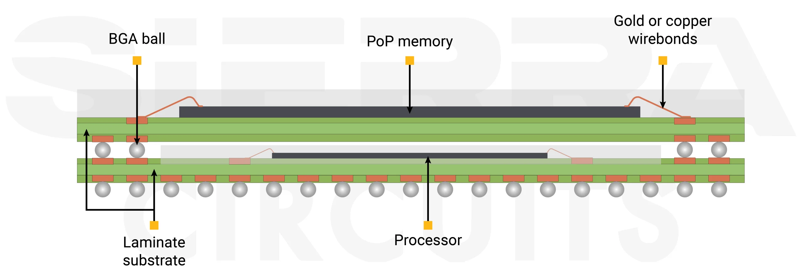
Package-on-package is used to stack multiple boards in humanoid robotics PCB assembly.
Embedded components to reduce interference
To further optimize PCB design, passive (resistors, capacitors) and active components (sensors, microcontrollers) are often embedded directly within the printed board layers.
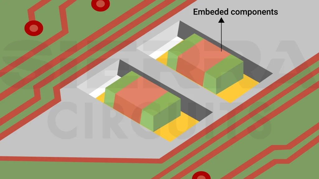
The benefits include:
- This integration reduces electromagnetic interference and improves signal transmission, enhancing robotic responsiveness.
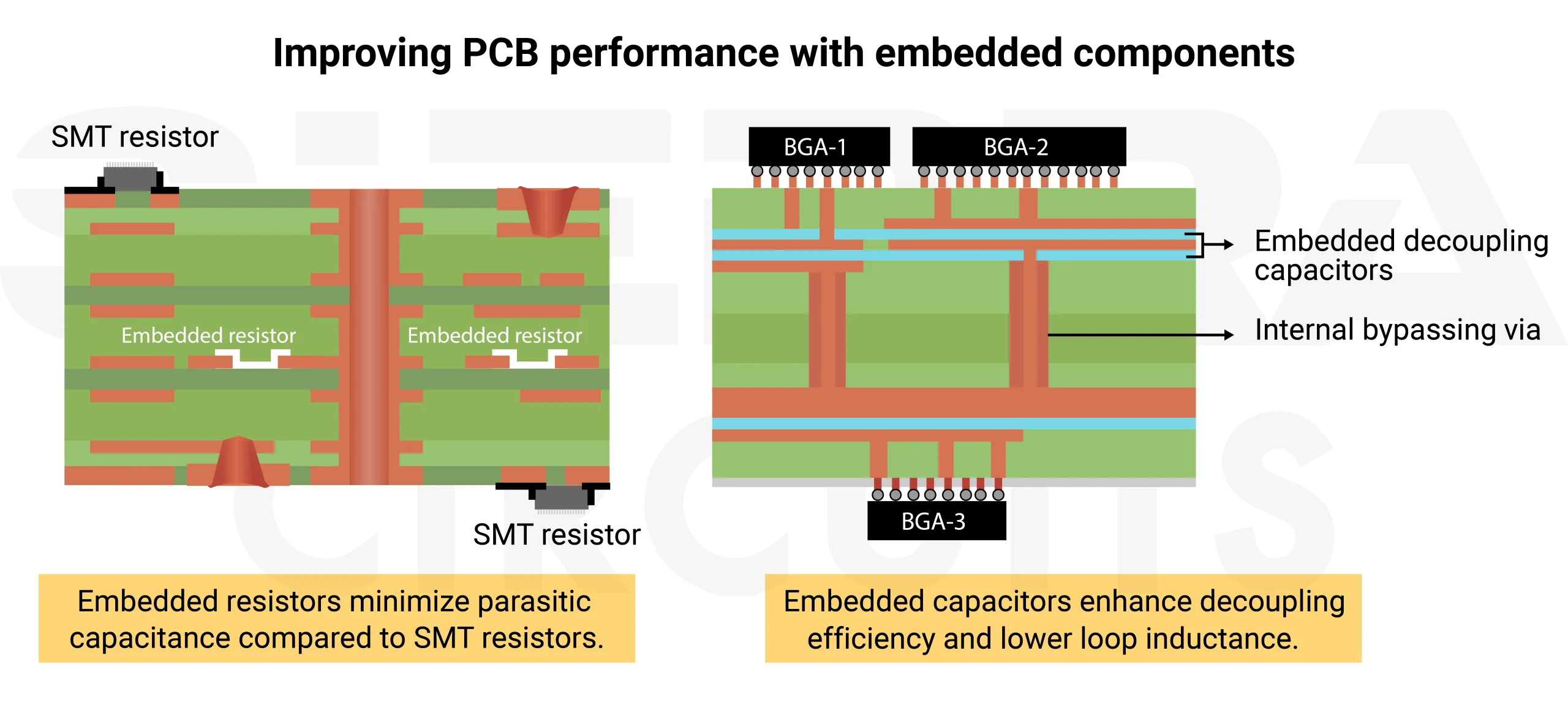
Embedded components can improve the performance of PCBs in humanoid robotics. - It improves mechanical stability, which is crucial for humanoid robots that undergo dynamic movements.
To learn more, see how to design a PCB with embedded components.
What are the electronic components used in humanoid robotics PCB assembly?
Robots rely on controllers, sensors, and actuators, all connected by printed boards for communication, power, and data processing. High-speed connectors play a crucial role in linking these components efficiently while ensuring high-speed signal transmission.
Here are the electronic component parts of humanoid robots:
1. Microcontrollers and processors for decision-making and motion control
The brains of a humanoid robot include MCUs (ATmega328P, ESP32, STM32) for control tasks, MPUs (NVIDIA Jetson, Intel Movidius) for AI applications, and FPGAs for real-time signal processing.
Humanoid robotics PCBs are designed to support different controller architectures, ranging from centralized to distributed systems.
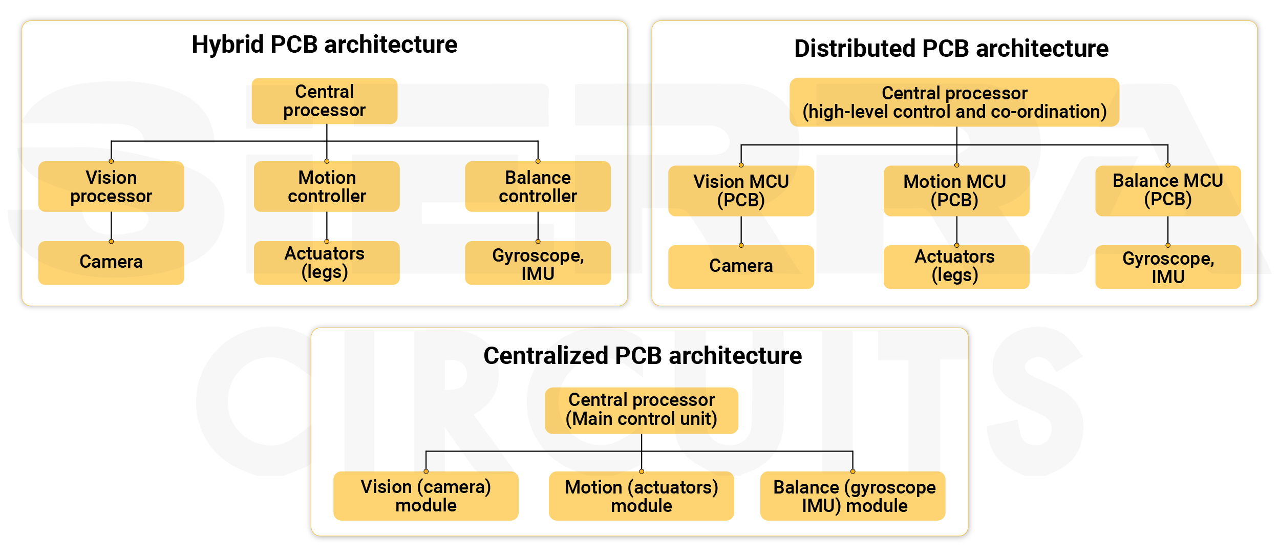
| PCB architecture | Description | Advantages | Challenges | Humanoid examples |
|---|---|---|---|---|
| Microcontroller-based subsystems | PCBs incorporate microcontrollers to manage individual subsystems like limb movement, balance, and sensor processing. | Power-efficient, compact, and handles localized sensorimotor tasks. | Limited processing power for complex computations. | Bioloid |
| Centralized | A single main PCB houses a high-performance processor that processes all sensor inputs and actuates movement. | Simplifies integration and reduces wiring complexity. | High computational load on one board, limits scalability. | ASIMO, early versions of NAO |
| Distributed | It has multiple microcontroller-based boards, each handling a specific subsystem (e.g., arms, legs, vision), communicating via I2C, SPI, CAN bus, or RS485. | Modular, scalable, and improves real-time performance. | More complex communication and synchronization between boards. | iCub |
| Hybrid (centralized + distributed | This model combines centralized processing (AI and decision-making) with distributed PCBs (motor control, sensors). | Balances computational efficiency and modularity. | Requires careful task allocation and communication management. | Atlas, Sophia |
The choice of architecture significantly influences the layout, PCB communication interfaces, and power distribution strategy.
2. Sensors for real-time perception and interaction
Sensors play a critical role in humanoid robots by providing real-time data for movement control, object detection, and environmental awareness. While some sensors are embedded directly in the board, others are external modules that interface with the PCB via wired or wireless connections.
| Category | Sensor type | Function | Examples | Connection type |
|---|---|---|---|---|
| Embedded PCB sensors | Inertial sensors (IMUs) | Balance and motion tracking | MPU6050, BNO055 | Directly soldered |
| Temperature sensors | Monitor heating, prevent overheating | LM35, TMP102 | Directly soldered | |
| Tactile sensors | Touch sensing for object manipulation and safety | Capacitive, resistive touch sensors | Integrated into flexible boards | |
| External sensors connected to the PCB | Proximity sensors | Obstacle detection and collision avoidance | Ultrasonic, IR, LiDAR | I2C, UART, SPI, CAN, Ethernet (for high-end LiDAR) |
| Vision and camera sensors | Visual perception | Monocular, Stereo, 3D cameras, LiDAR | CSI, USB, MIPI, Ethernet (for high-speed LiDAR) | |
| Force-torque sensors | Grip strength and contact pressure measurement | Used in robotic hands and limbs | I2C, SPI, CAN, EtherCAT (for industrial applications) | |
| GPS modules | Outdoor navigation | GPS receivers | UART, I2C |
Additional PCB design considerations for sensor integration
- Make sure your board supports multiple data buses like I2C, SPI, UART, and CAN for sensor communication.
- Some sensors(IMU and temperature sensors) require amplifiers, filters, or ADCs (analog-to-digital converters) to convert raw signals into usable data.
- Sensors have different voltage and current requirements, so voltage regulators and power distribution networks must be designed accordingly.
Further, IoT-enabled printed boards enhance real-time communication between sensors, improving perception and decision-making. They allow humanoid robots to gather and process environmental data autonomously.
3. Motor control systems for precise limb movement and actuation
In humanoid robots, motors and actuators are essential for movement, but not all motor-related components are directly mounted on the PCB. Instead, the board serves as the control hub, managing power distribution, signal processing, and motor driver circuitry.
| Component | Function | Examples | Connection type |
|---|---|---|---|
| Motor driver ICs | Control DC motor operation and regulate power | L298N, TB6612FNG, VNH2SP30 | Surface-mounted / through-hole |
| MOSFETs and H-bridge circuits | Custom motor driver configurations for high-power applications | IRF3205, IRLZ44N (MOSFETs) | Surface-mounted / through-hole |
| Microcontrollers | Send PWM signals to control motor (servo) speed and direction | ESP32, STM32 | Surface-mounted / through-hole |
| Stepper motor drivers | Drive stepper motors with precise control | A4988, DRV8825, TMC2209 | The plug-in module is usually mounted on separate breakout boards |
| Gate drivers | Amplifies and controls switching signals for high-power transistors (MOSFETs/IGBTs) | IR2110, TC4420 | Surface-mounted |
Servo, stepper, and DC motors are not directly mounted on a PCB due to their size, power requirements, and heat generation. Instead, they are externally connected through motor drivers or controllers.
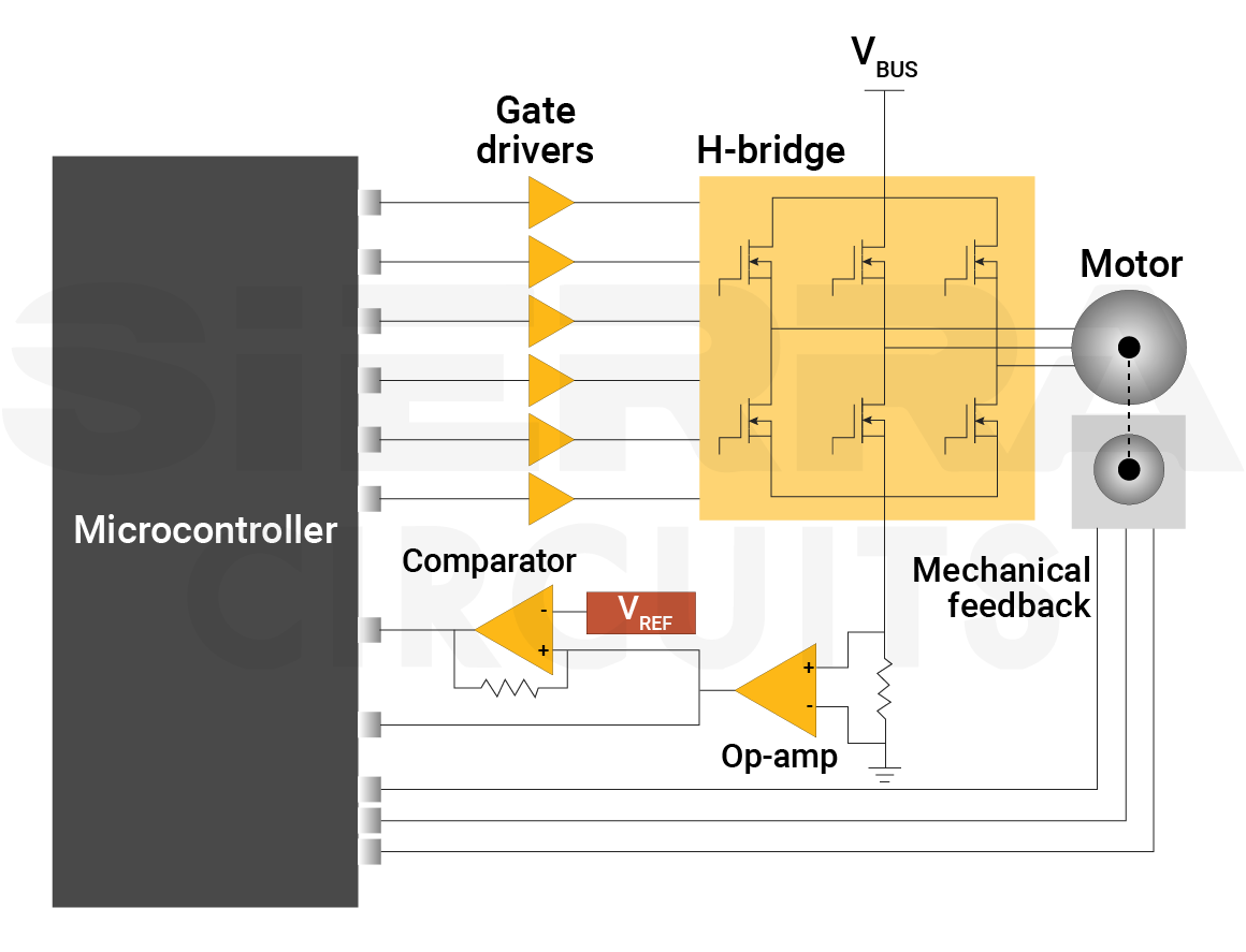
Servo motors receive PWM signals directly from the main control board, while stepper motors require dedicated driver modules (e.g., A4988, DRV8825) that are either mounted on the board or inserted into a breakout module for connectivity.
DC motors rely on motor driver ICs (e.g., L298N, TB6612FNG) or H-bridge circuits on the motor driver PCB to control speed and direction. The board acts as the control hub, managing signals and power but not physically housing the motors.
For motor integration, incorporate reliable connectors (JST, screw terminals), efficient PCB heat dissipation techniques (heat sinks or separate power boards), and wide traces to handle high currents.
4. Power management components to ensure stable energy distribution
Humanoid robots require stable and efficient power management to drive motors, sensors, controllers, and communication modules. The power requirement varies based on the size, number of actuators, and computational needs.
Most medium-to-large humanoid robots require a battery pack in the range of 12V – 24V with a capacity of 5Ah – 30Ah, depending on motor count and processing needs.
The battery pack (Li-ion/Li-Po, 12V–24V) is the main power source for a robot. It connects to the PCB using XT60, XT90, or JST connectors and supplies a regulated voltage to various subsystems.
Further, a battery management system (BMS) ensures safe charging and discharging by monitoring voltage, current, and temperature, preventing short circuits. ICs like BQ76952 or LTC6804 control the BMS and communicate with the PCB through I2C or SPI.
| Components | Function | Examples | Connection types |
|---|---|---|---|
| Voltage regulators | Converts high battery voltage to required system voltages (e.g., 12V to 5V, 3.3V) | LM7805, LM317, MP1584, buck converters | Surface-mounted / through-hole |
| DC-DC converters (buck/boost) | Steps the voltage up (Boost) or down (Buck) for power efficiency | XL6009, LM2596 | Surface-mounted / through-hole |
| Current sensors | Monitors power consumption to prevent overloads | ACS712, INA219 | Surface-mounted / through-hole |
| Capacitors (electrolytic, MLCCs) | Filters voltage ripples and stabilizes power lines | 100µF Electrolytic, 0.1µF MLCC | Through-hole (electrolytic), Surface-mounted (MLCC) |
| Fuses and TVS diodes | Protects against overcurrent and voltage spikes | 5A-20A fuses, TVS diodes | Through-hole (fuses), Surface-mounted (TVS diodes) |
The power distribution module (PDM) manages and distributes power from the battery to various subsystems in a high-power humanoid robot. It integrates DC-DC converters, MOSFETs, relays, and current sensors to regulate voltage and protect against overloads.
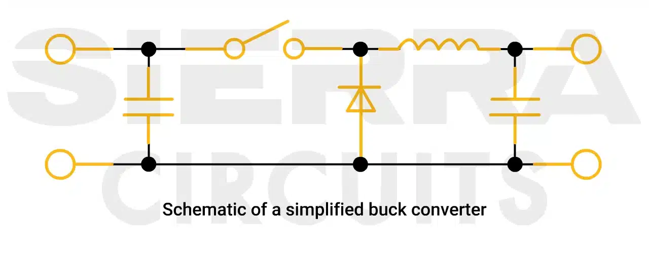
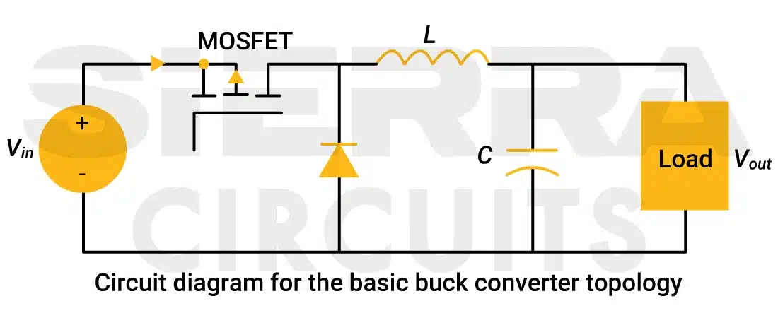
The PDM connects to the main PCB and motor control boards via high-power connectors like XT60, XT90, or screw terminals, ensuring efficient and safe power flow.
5. High-speed and high-power connectors for compact boards
In humanoid robots, specialized PCB connectors are required to handle high mobility, compact spaces, and high-speed data transmission.
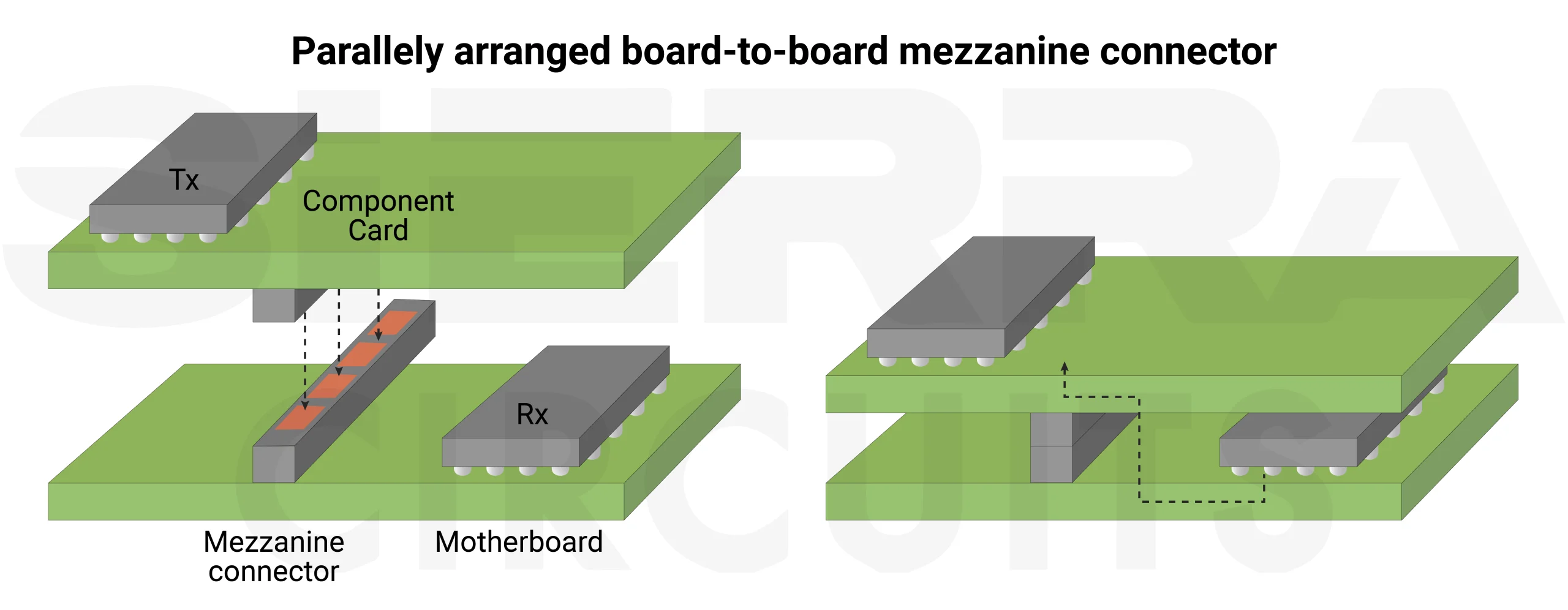
Below are key connector types specifically used in humanoid applications:
| Connector type | Function | Application in humanoid robots | Mounting type | Key features |
|---|---|---|---|---|
| Micro coaxial (MIPI CSI/DSI) | High-speed data transmission for camera and display interfaces. | Used for vision systems like cameras and displays in the humanoid head. | Surface-mounted | Compact, high-speed, and supports MIPI interfaces. |
| FPC/FFC (flexible flat cable) | Provides flexible cable connections in robotic joints and compact spaces. | Essential for joints and articulated limbs, enabling signal transmission while allowing movement. | Surface-mounted | Flexible, space-saving, and supports high-density circuits. |
| High-power motor connectors (XT30, XT60, Amass AS150) | Handles high current for robotic limb actuation. | Used in servo and brushless motor PCBs for robotic limbs. | Through-hole / screw terminals | High current capacity, secure connections, heat-resistant. |
| Board-to-board mezzanine (Hirose DF40, Samtec Q-Strip) | Enables PCB stacking for modular board designs. | Found in modular humanoid architectures, allowing detachable PCB stacking. | Surface-mounted | Compact, high-speed signal transfer, modular design. |
| Hall effect and encoder connectors (JST XH, Molex PicoBlade) | Provides precise motion feedback for sensors. | Used in precision motion control for robotic fingers and legs. | Through-hole / surface-mounted | Reliable, compact, and supports low-power sensor integration. |
| Edge card connectors (PCIe, gold finger) | Allows AI module upgrades by connecting processing PCBs. | Applied in AI-driven processing units for upgradable GPU/FPGA integration. | Edge-mounted | High-speed data transfer, durable, modular. |
These high-speed connectors for humanoid robotics ensure compactness and durability.
Download our eBook to learn the basics of PCB connectors.
Connector Design Guide
5 Chapters - 32 Pages - 50 Minute ReadWhat's Inside:
- Basics
- Terminology
- Selection and layout rules
- Testing
- Application-specific PCB connectors
Download Now
The impact of GaN technology on humanoid robotics
Precision motion is critical for humanoid robotics, particularly in small joint actuation. Gallium Nitride (GaN) technology is revolutionizing robotics by offering higher efficiency, faster switching speeds, and improved power density compared to traditional silicon-based electronics.
Humanoids require compact and efficient power electronics circuit boards due to their limited joint space. The power board, often a ring-shaped PCB with a diameter of just 5–10 cm, must accommodate multiple components, including the motor, reducer, encoder, and sensors. Achieving stable and high-power motor control within such constraints is a significant design challenge.
GaN power devices offer several advantages over silicon-based MOSFETs:
- A smaller die area, due to lower specific resistance, allows for higher power density.
- Reduced power losses translate to less heat generation and longer operational lifespans.
- Smaller devices allow for more compact designs, a crucial factor in robotics.
- Faster response times enable precise motor control, critical for applications such as robotic toes, which require quick adjustments to maintain balance and fluid motion.

GaN Power capability versus switching frequency for high voltage power devices.
4 key benefits of GaN in motor control
- GaN devices switch 10 to 100 times faster than silicon MOSFETs, enabling motors to operate at higher frequencies, reducing energy losses, and improving efficiency.
- Faster switching speeds allow the use of smaller ceramic capacitors instead of bulky electrolytic capacitors, reducing the overall size and weight of motor drive systems.
- Gallium nitride minimizes dead time from several hundred nanoseconds to just a few, increasing torque per ampere and leading to more efficient, quieter motor operation.
- Unlike silicon MOSFETs, GaN devices do not suffer from reverse recovery charge, preventing energy losses and excessive heat generation during switching cycles.
5 advantages of integrating GaN in LiDAR systems
- GaN’s ultra-fast switching speed enables LiDAR systems to emit and detect laser pulses at higher frequencies, significantly improving resolution and frame refresh rates.
- The increased pulse frequency allows robots to generate more detailed and precise environmental maps, improving navigation and obstacle detection.
- It provides higher current density when compared to its silicon counterpart. Hence, GaN supports stronger laser pulses, crucial for long-range detection where signals must travel farther while maintaining strength.
- GaN’s ability to handle high power in a smaller footprint enables the development of space-efficient LiDAR systems that integrate seamlessly into humanoid robots.
- Its chip-scale packaging minimizes unwanted electrical effects that can degrade LiDAR performance, ensuring greater system reliability.
Key takeaways:
- Integrate advanced PCB architectures for communication between microcontrollers, sensors, actuators, and power management systems in humanoid robots.
- Incorporate diverse sensor technologies, such as IMUs, vision cameras, and force-torque sensors, for real-time perception and adaptive interaction.
- Implement efficient motor control systems using motor driver ICs, MOSFETs, and gate drivers to ensure precise limb movement and actuation.
- Leverage GaN technology to enhance power efficiency, reduce heat dissipation, and improve motor control in humanoid robotics.
- Adopt advanced PCB assembly techniques, including vapor phase soldering, laser soldering, and AI-driven pick-and-place systems, to improve precision and durability.
- Utilize 3D component stacking and embedded PCB components to optimize space and enhance mechanical stability in humanoid designs.
Humanoid robots require advanced PCB architectures for the integration of controllers, sensors, actuators, and power systems. Advancements in PCB assembly, GaN technology, and miniaturized components are enhancing efficiency, intelligence, and agility.
These innovations are shaping the future of robotics, enabling lifelike movement, real-time decision-making, and improved human interaction.
Connect with us to get your robotics PCBs manufactured with precision.
Have questions on robotics PCB design? Post your queries on SierraConnect. Our PCB experts will answer them.





Start the discussion at sierraconnect.protoexpress.com