Contents

On-demand webinar
How Good is My Shield? An Introduction to Transfer Impedance and Shielding Effectiveness
by Karen Burnham
Flex PCBs are used in medical devices and wearables as they offer some great advantages. To begin with, they are smaller, lighter, and more durable.
Fitness wearables and medical devices have become more popular nowadays. The demand for these devices is expected to increase even more in the upcoming years. Fitness wearables and medical devices have something in common. Both require flex PCBs.
Why are flex PCBs used in medical devices and wearables?
A key trend among both medical devices and wearables is miniaturization—these gadgets need to be as small as possible while still reliably performing their designated functions.
Flexible circuits address various challenges faced by the PCB manufacturers. One of the prominent features of flex PCB is it allows the PCB manufacturers to manufacture smaller devices. Let us have a look at a few main reasons why flex PCBs are used in medical devices and wearables.
Dynamic flexing
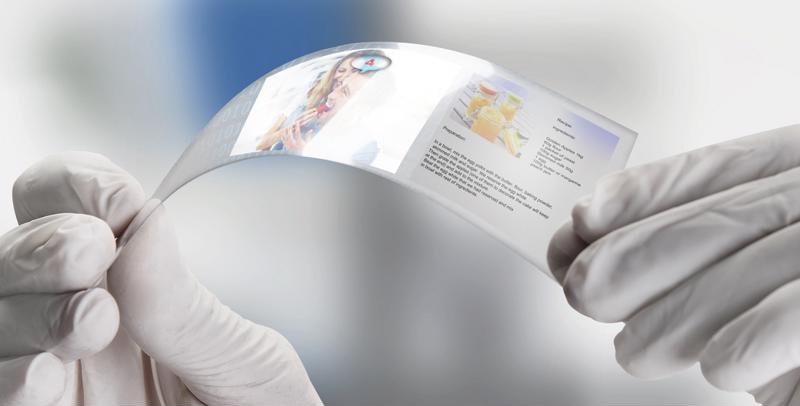
Flexible PCBs have an extraordinary flexing or bending ability. Medical devices generally expand/contract during their operations. The flexing property of the flexible PCBs makes it ideal for medical applications. This property is also advantageous for the applications that are connected through a hinged device. Flexibility is particularly challenging for the designers in the healthcare industry because this has not been a major consideration for medical electronics in the past. Most of the earlier medical devices used to be larger and more rigid. With the advent of flex circuits, medical devices are evolving to be more compact, durable, and flexible.
To know more about the advantages that the flex PCBs offer read our article The Advantages of Flex PCBs And Their Applications.
Reliability
Reliability is the ability of a system to consistently perform its required function without degradation or failure. Reliability becomes very critical in medical applications and wearables. Generally, points of interconnects are a potential source of electronic failures. Flexible circuitry minimizes the connection points and simplifies the assembly. This characteristic of flex circuits eliminates the chances of interconnecting defects like poor solder joints. Flexible PCBs are basically made of polyimide materials. These polyimide PCB materials are resistant to a wide range of environmental and chemical changes. The flex PCB material’s ductility and flexibility minimize the impact of shock and vibrating events.
Electrical reliability
Flex PCB materials are essentially well suited for high-speed signal applications. The following features of the flex PCBs make them electrically reliable:
- Improved dielectric constant as compared to standard rigid materials.
- Uniform material thicknesses
- Uniform trace width and spacings.
Space and weight
One of the dynamic features of new-age medical devices and wearables is miniaturized size. These gadgets need to be as small as possible at the same time they should perform the required functions. The increasing demand for such miniaturized devices in the medical industry makes the flexible PCBs a perfect choice for such devices. The flexible circuits have thinner copper layers and insulating layers. Due to this the bend radius of the flex PCBs can be as minimum as required. As a result, these PCBs can adapt to tighter spaces.
High-density capabilities
HDI flex PCBs are simply a flex PCB with a higher number of interconnections with minimal space. The flex HDI design incorporates dense component placement and versatile routing. The advantages of flex HDI PCBs are numerous. Let us have a look at some advantages of HDI flex PCBs:
- Flex HDI boards are ideal where weight, space, and reliability are primary concerns. This makes HDI flex PCBs very much suitable for medical devices and wearables.
- The presence of blind buried and micro vias reduce the space requirement drastically. This also results in better signal integrity.
- The HDI boards are cost-effective. The functionality of an 8-layer rigid board can be achieved by a 6 layer HDI board.
To know more about flex design considerations read our article Avoiding Common Flexible PCB Errors and Designing for Success.
Applications of Flex PCBs in medical devices
Flexible PCBs are not only more flexible than rigid PCBs, but they can also be lighter, smaller, and more durable.

Medical wearables: The flex PCBs are used in various activity trackers such as health activity monitoring systems.
Implantable medical devices: Devices that can be implanted into the human body are called implantable devices.
Hearing-assist devices: Flex PCB design allows engineers to mount the microphone, DSP, and battery in a tiny, compact package that fits behind the ear.
Diagnostic equipment: The equipment which is used for CT scanning, MRIs, ultrasound scanners use flex PCBs.
Monitoring devices: These devices consist of portable electronic devices that monitor human vitals such as heart rate, blood pressure, blood sugar rate, and body temperature.
Advantages of flex and rigid-flex PCBs in medical devices
Flex PCBs have mechanical advantages over rigid PCBs in various medical applications.
- Flex PCBs allow the engineers to mount the various electronic components like microphone, battery, camera in a tiny and compact package. As a result, the entire end product (medical device) can be placed on a human body (for example, hearing-assist devices).
- A flex circuit can be formed in complex shapes in three dimensions with branches to multiple connectors, which would be impossible to achieve with a rigid PCB.
- Flex circuits can be interfaced with rigid boards without the relatively tall and bulky connectors flat cables require, or in the case of rigid-flex construction.
- They can be integral with the boards and eliminate external connectors altogether.
All of these unique features of flex and rigid-flex circuits have made a perfect suit for wearables and medical applications.
Flex PCBs have evolved over time. Now, they are being used in the medical industry for applications including medicine delivery systems and wristwatches that can keep tabs on circulatory and respiratory system data and send it to the wearer’s cardiologist.
The flex PCBs used in the above-mentioned applications are becoming tinier, which can create some significant challenges in the PCB process. This forces the manufacturer to opt for finer lines and spaces, thinner copper, thinner base material, and all of this really has to do with the application.
To know more about flex PCB manufacturing class, read our article Choosing IPC Class for Medical Flex PCBs
How to get through the design challenges of medical and wearable devices?
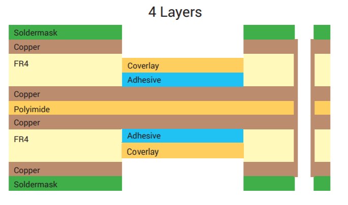
Wearables and medical devices that can be attached to the human body demand flex circuitry and high-density layouts. Also, the shape of the PCB is more or less round, elliptical. Sometimes, the PCB may be of irregular shape. These requirements make a PCB designer to call for clever component placement and effective routing. Incorporating rigid-flex PCBs into such compact and high-density designs enable the designers to handle the odd shapes easily. A sample stack-up of a rigid-flex PCB is shown below. In this stackup, two 4-layer rigid boards on the left and right are connected using a single-layer flex circuit. The number of layers and the materials used for your rigid-flex design plays an important role.
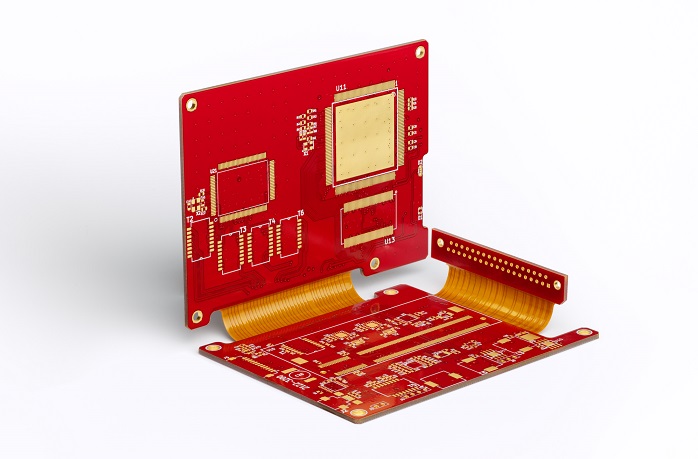
The image below shows a typical rigid-flex PCB. It has 3 rigid PCBs interconnected through flex circuits. Rigid-flex PCBs can be folded to fit into a small 3-dimensional space in the final product. One more major aspect of the rigid-flex PCBs is its bendability/flexibility.
The flexibility of a flex section is defined by its bend radius. Bend radius is the minimum amount the flex area can bend. Use the chart below to calculate the bend radius on your next design.
| Number of layers | Bend radius (mils/mm) |
|---|---|
| 1 (single-sided) | Flex thickness x 6 |
| 2 (double-sided) | Flex thickness x 12 |
| Multi-layer | Flex thickness x 24 |
In some applications, the flex sections of the rigid-flex PCBs are subject to flex frequently. This gives rise to numerous issues that are not encountered in the rigid section of the rigid-flex PCB.
Flex PCB design tips
Below are a few quick design tips to overcome the challenges associated with flex circuits.
Increase the reliability of the flex trace: In dynamic applications, the flex section is regularly flexed and twisted. That means the copper traces on the flex section are more likely to delaminate. Sierra Circuits recommends the use of anchors or spurs. During dynamic bending, anchors help stabilize the outer layer. Sierra Circuits also highly recommends using teardrops on all flexible PCBs. Teardrops can reduce and even eliminate potential stress concentration points on the PCB.
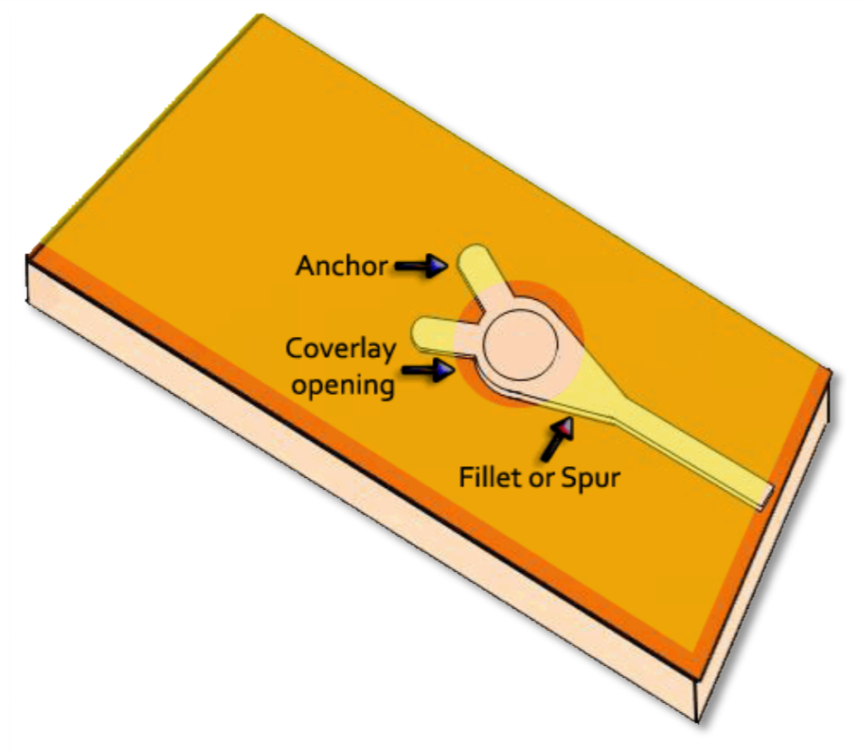
Using teardrops not only strengthens the pad and the traces to prevent delamination, but it also provides better yield during manufacturing by increasing the drilling tolerance.
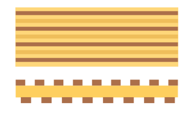
Traces should be offset on double-sided flex circuits: Placing the traces on top of each other on a double-sided flex circuit will not only reduce the flexibility of your circuit, but it will also increase stress on the copper traces. To evenly distribute the stress Sierra Circuits recommends to stagger the flex traces as shown below.
Avoid sharp angles on traces: Sharp trace corners are subject to be more stressed than the straight path. Straight paths also reduce delamination problems. When there is a requirement to change the direction of the trace, Sierra Circuits recommends having curved traces as shown below.

Flex PCBs offer numerous advantages for the designers to produce flexible, compact, and efficient electronic products. They also improve reliability and reduce the requirement of connectors between different electronic subsystems. This elimination of the connectors reduces the chance of interconnection issues. Sierra Circuits’ flexible printed circuit board services include flexible prototypes, high-tech quick turn flex PCBs, and HDI for flex. We offer single-layer, double-layer, rigid-flex, multilayer, and HDI flex PCBs.
To know more about flex PCB design, read our article 5 Must-Knows for Your First Flex PCB Design.
Flex PCB Design Guide
10 Chapters - 39 Pages - 45 Minute ReadWhat's Inside:
- Calculating the bend radius
- Annular ring and via specifications
- Build your flex stack-up
- Controlled impedance for flex
- The fab and drawing requirements
Download Now


